Why Britain's Installed Base Still Runs on Displays Nobody Makes Anymore
The United Kingdom's manufacturing sector carries an unusually deep installed base of durable capital equipment. A Platt textile machine, a Colchester lathe, a Denford CNC router, a Molins packaging line, a Camber ring spinner, a Holroyd gear grinder — machines of this class were built to run for thirty years or more, and many are still in daily production. Their mechanical assemblies, castings, gearboxes and spindles are rebuildable almost indefinitely. What ages them out is not iron. It is the small display module sitting in the operator panel, a part built by a Japanese or European supplier in 1994, discontinued in 2008, and now unobtainable in any meaningful quantity.
When that display fails — dead backlight, cracked glass, failed driver IC, or an STN panel that has gone brown and sluggish at low temperature — the owner is often told the machine is uneconomical to repair. In practice, the machine is fine. The display is the problem, and a custom-engineered replacement is usually a small fraction of the cost of a new machine and a fraction of the downtime of a full control retrofit.
What Actually Fails, and Why Generic Replacements Rarely Fit
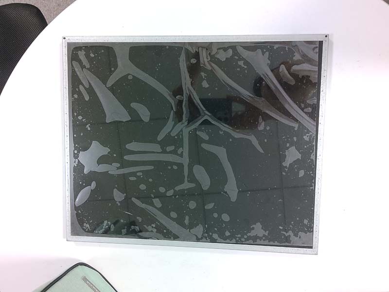
The classic failure modes are well understood. Electroluminescent (EL) backlights on 1980s and 1990s modules lose luminance steadily; a panel that produced 100 cd/m² when new may be down to 15 cd/m² after two decades, long before the glass itself fails. CCFL backlight inverters fail at the transformer or at the cold-cathode tube. STN and FSTN fluid degrades with UV exposure and thermal cycling, producing the characteristic brown, low-contrast look. Driver ICs on tape-automated bonding (TAB) suffer from thermal-cycling fatigue at the bond joints. And the polariser, particularly on machines near washdown areas or solvent vapours, delaminates.
The obstacle to simply buying a modern equivalent is that legacy industrial modules were rarely standard catalogue items. A typical module on a British-built machine may present a 240×64 or 320×240 pixel format, a 4-bit or 8-bit parallel interface with an unusual chip-select polarity, a single 5 V rail with an on-board negative voltage generator for the STN bias, a non-standard 20-pin or 24-pin FPC with a 0.5 mm or 1.0 mm pitch, and a mechanical outline sized to a stamped panel aperture that nobody is going to re-machine. Substituting a generic module means either modifying the machine or compromising reliability. Neither is acceptable in a plant running three shifts.
The Practical Route: Reverse Engineering Before Specification
A competent custom replacement programme begins with the machine, not the catalogue. The first step is to document the original module in situ: photograph the front and rear, measure the active area, the outline, the mounting hole pattern, the connector position, the flex tail length and the bezel depth. Pinout is then established empirically with a logic analyser or oscilloscope during a normal machine cycle, capturing the interface type, the data bus width, the timing envelope, the reset and chip-select sequencing, and the backlight supply characteristics. The controller family matters — a SED1335/RA8835 class controller behaves very differently from a T6963C or an Epson S1D13700, and the replacement must either be pin-compatible at that level or absorb the difference in an adapter stage.
From that documentation, a replacement is engineered as a three-part assembly: a modern display glass selected for the required optical and thermal performance, a controller and interface board that reproduces the original electrical behaviour exactly, and a mechanical frame or carrier that presents the same footprint to the machine panel. Where the original used a 5 V logic interface and the modern panel uses 3.3 V, level shifting is handled on the adapter; where the original relied on an EL or CCFL backlight, a constant-current LED driver with PWM dimming takes over. The machine's control software should not know the display has changed.
Optical Performance on the Factory Floor
Standard catalogue displays are designed for office lighting. A British machine shop, foundry, glassworks or food hall is a different optical environment: overhead sodium or LED high-bays, skylights, open roller doors, and reflective coolant or washdown surfaces. A replacement module specified at 250 cd/m², which looks acceptable on a bench, becomes unreadable when a 15,000 lux highlight lands on the bezel. This is where high-brightness engineering earns its place.
For panel-mount HMI positions, luminance in the 800–1,500 cd/m² range, combined with an anti-reflective front polariser and, ideally, optical bonding of the glass to the cover lens, removes the internal air gap reflections that cause washout. Bonding also improves contrast under angled viewing and increases mechanical robustness against vibration and impact. Where the machine is operated through a protective window, the cover material and coating should be specified together with the display, since a poorly matched window can cost more luminance than the display upgrade gains. For intrinsically dark environments such as night-shift control rooms in rail or utilities, the same module should support wide-range PWM dimming so that brightness can be reduced without flicker or colour shift.
Thermal, Environmental and Sealing Requirements
British industrial environments are rarely extreme in any single dimension, but they are frequently harsh in combination: cold starts below freezing in unheated workshops or outdoor pumping stations, condensation during spring warm-up, vibration from nearby presses, and mist from coolant or high-pressure cleaning. A replacement display intended for these conditions should be qualified to an operating range of at least −20 °C to +70 °C, and to −30 °C where the machine is in an unheated exposed location. Below roughly −10 °C, STN fluid response slows visibly; designs intended for cold starting should either use a panel with an extended low-temperature specification or incorporate a small heater element behind the module with a thermostatic control.
Sealing is governed by BS EN 60529. Where the original operator panel carried an IP54 or IP65 rating, the replacement assembly must preserve it — the seal is a function of the frame, gasket and cover lens, not the display alone, and a replacement that fits mechanically but breaks the seal will fail the first washdown. Environmental and mechanical robustness testing follows the BS EN 60068 series, covering dry heat, cold, damp heat cyclic, sinusoidal and random vibration, and shock.
Compliance, Safety and the UK Regulatory Position
Replacing a display in an existing machine is normally treated as maintenance or a like-for-like repair rather than placing a new product on the market, so a full re-certification exercise is usually not triggered. Two caveats apply. First, the repair must not degrade the safety of the machine: under the Provision and Use of Work Equipment Regulations 1998 (PUWER), the duty holder must ensure work equipment remains safe and suitable, and the installer must not defeat interlocks, guards, emergency stops or safety-related indications carried on the display. Second, if the display forms part of the machine's EMC-relevant electronics, the replacement should be designed to the same immunity and emission envelope as the original — typically EN 61000-6-2 for immunity and EN 61000-6-4 for emission in industrial environments, or EN 61326-1 where the equipment is measurement or control apparatus — so that the machine continues to satisfy the UK EMC Regulations 2016.
Where a machine is being substantially rebuilt, or where a display replacement is supplied as a standalone product, UKCA marking obligations under the relevant regulations apply, and the supplier must be able to provide a technical file, a Declaration of Conformity, and RoHS and WEEE compliance evidence. For equipment operating in potentially explosive atmospheres, any display assembly entering a hazardous area must respect the zone classification and the existing certification of the enclosure; display replacement in a Zone 1 or Zone 2 panel is a specialist exercise and should never be treated as a generic swap.
Lifecycle Planning: Buying Time and Buying Ahead
The economics of display replacement are usually obvious once downtime is costed. A packaging or moulding line losing £400 per hour throws away the cost of a custom display module in under two shifts. Beyond the immediate repair, plant engineers should treat operator interfaces as a managed obsolescence risk. Capturing a pinout photograph and a full interface recording while a machine is still running — rather than after it has failed — is one of the cheapest engineering insurance policies available, because it removes the reverse-engineering hours from the critical path of a breakdown. For fleets with several identical machines, a single validated replacement design can be held as a stocked spares item and rolled out across the fleet on a planned basis rather than an emergency one.
Frequently Asked Questions
Can a discontinued display be replaced if no datasheet or pinout exists?
Yes, and this is the normal case rather than the exception. Where documentation is missing, the interface is characterised empirically: the original module is powered in the machine or on a bench rig and the control signals — data bus, chip select, read/write, reset, frame or line clock, and backlight supply — are captured with a logic analyser across a full operating cycle. The active area, outline, mounting pattern and flex tail are measured directly. That record is sufficient to design an adapter board that reproduces the original electrical behaviour and a carrier frame that reproduces the mechanical fit. The only situations that genuinely block a replacement are a failed display whose interface cannot be observed even on a substitute controller, or a custom ASIC inside the module performing an undocumented function, both of which are rare in operator-panel displays of this era.
Will a modern high-brightness TFT fit behind the original bezel and connect to the existing harness?
In most cases it can be made to fit, but rarely without a designed interface stage. Modern high-brightness panels typically use a 3.3 V logic interface, an LVDS or RGB TTL input rather than a legacy 4-bit or 8-bit parallel bus, and a constant-current LED backlight rather than an EL or CCFL supply. The adapter board bridges all of these: it converts the incoming legacy bus into the panel's native input, translates logic levels, generates any required bias voltages, and drives the backlight from the machine's existing supply with appropriate current limiting. Mechanically, the new glass is mounted in a machined carrier that presents the original aperture, hole pattern and connector position, so the panel cut-out and the front bezel are untouched. Where the original active area is smaller than the nearest modern equivalent, the carrier masks the surplus area with a bonded bezel so that the visible image region matches the original.
Does fitting a custom replacement display require the machine to be re-certified?
Usually not, provided the replacement is a genuine like-for-like repair that preserves the original function and does not alter safety-related behaviour. Replacement of a failed component with an equivalent is treated as maintenance, and PUWER places the emphasis on the machine remaining safe and suitable for use rather than on a fresh conformity assessment. What does change obligations is a substantial rebuild, a change of function, or supply of the display as a standalone product placed on the UK market — in those cases UKCA marking, a technical file and a Declaration of Conformity are required. As a matter of good practice, retain the design record, the interface measurements, the EMC test evidence and the installation notes so the machine's technical file remains complete and any future audit or insurance inspection can be satisfied.
What is a realistic lead time and minimum order quantity for a custom display replacement?
For a well-documented adaptation of an existing panel platform — a new carrier frame, a custom interface board and firmware configuration — tooling and first-article build typically run in the region of six to ten weeks, with a further short cycle for verification on the customer's machine. Designs requiring a bespoke glass mask, a non-standard pixel format or a fully custom controller add several weeks and carry meaningful tooling charges. Minimum order quantities are driven almost entirely by the tooling: adapter boards and machined carriers scale efficiently, so a pilot batch of ten to fifty units is normally viable, while a custom glass or bespoke touch stack will usually require a minimum in the low hundreds. Where a plant operates a fleet of identical machines, specifying one replacement design for the whole fleet almost always reduces unit cost and eliminates repeated reverse-engineering effort.
KEYWORDS: custom LCD replacement, industrial display retrofit, high brightness LCD, legacy machine HMI, obsolete display replacement