Why Bar LCD Cross-Referencing Has Become a Standing Task on UK Design Desks
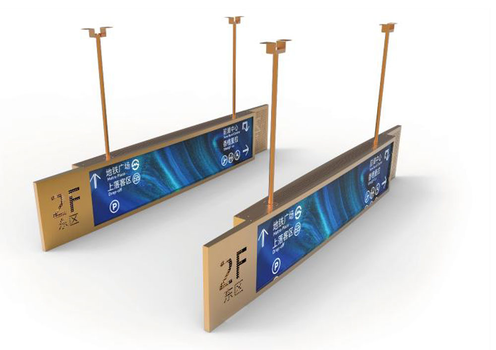
Stretched or "bar" format LCDs have moved from novelty to default in a long list of British-made equipment: passenger information columns on rail platforms, queue displays over checkout lanes, vending fascia, gym and gaming consoles, lab instrument front panels, telematics stacks in off-highway vehicles, and the slim status strips built into medical carts. The format is attractive because it puts a wide, short window into a mechanical envelope that a 16:9 panel simply cannot fill — a 480 mm tall cabinet front wants a 37 : 9 strip across the top, not a 21-inch desktop monitor.
The engineering consequence is that almost nobody designs a bar LCD from a clean sheet. Panels are sourced from a small pool of fabs, many of them running automotive or industrial glass that reaches end-of-life on a three-to-five year cadence, often with a last-time-buy notice and no drop-in successor. When a UK equipment manufacturer gets that notice, the question is never "which panel is best?" but "which panel can I drop into a chassis, harness and firmware stack that are already in the field?" That is a cross-reference problem, and it is best solved with a structured method rather than a datasheet hunt.
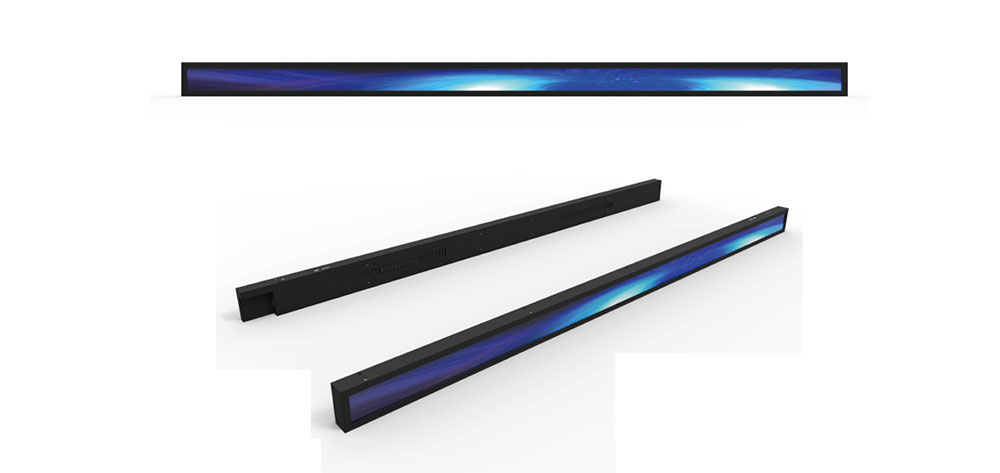
What Actually Defines a "Bar" Panel
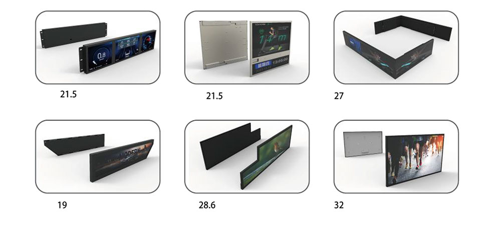
Suppliers and buyers use the term loosely. For cross-reference work, treat it as a mechanical descriptor first and an electrical one second. A bar LCD is any panel whose active area aspect ratio is wider than roughly 3 : 1, typically 8 : 3, 16 : 3, 32 : 9 or 37 : 9. Common active areas in current distribution include approximately 6.5 in, 8.8 in, 12.3 in, 16.9 in, 23.1 in, 28 in, 36.6 in and 48.5 in diagonals, with native resolutions such as 1280 × 480, 1440 × 320, 1920 × 480, 1920 × 540, 2880 × 864 and 3840 × 1080. Note that "diagonal" is a poor primary key here: a 1920 × 480 strip from two different fabs can differ by several millimetres in both directions.
Two panels are only candidates for a direct swap when the active area matches to within about ±0.3 mm in both axes. If the active area grows, the bezel aperture must grow; if it shrinks, the customer sees a visible inner frame or a masked border that no longer lines up with the window graphic. Outline dimensions are more forgiving, because a smaller outline can be shimmed, but thickness is not — a millimetre of extra depth can foul a touch stack, a gasket, or a heatsink.
Step 1 — Build the Mechanical Envelope Before You Look at Any Datasheet
Start from the existing design, not from the supplier catalogue. Extract the following from the original drawing and the physical unit:
- Active area width × height (mm), and the tolerance the window gasket or OCA bond can absorb.
- Outline width × height × thickness, including any protrusion at the driver IC fold or the FPC exit point.
- FPC exit side and orientation — top, bottom, left or right — and whether the connector is on the front or rear face.
- Mounting boss positions and thread type; frame screw depth available behind the panel.
- Bezel width on all four edges, and whether the design relies on the panel's own bezel or on a machined mask.
- Clearance for the backlight heatsink or thermal pad, plus the air gap to the rear enclosure wall.
A quick sanity check that saves weeks: place the proposed part's outline drawing on the chassis drawing at 1 : 1 and look specifically at the FPC exit. Reversed FPC entry is the single most common reason a mechanically perfect cross-reference fails at first fit, because the harness has to fold back across the panel and the bend radius goes below the 1 mm minimum in the panel specification.
Step 2 — Optical Matching: Brightness, Uniformity and Viewing Cone
Brightness is where cross-references quietly change the product's behaviour. A bar LCD specified at 500 cd/m² for an indoor vending fascia cannot be replaced with a 250 cd/m² equivalent without the customer noticing in a brightly lit store, and it cannot be replaced with a 1500 cd/m² outdoor part without re-checking thermal margins, power budget and the dimming curve in firmware.
- Indoor / sheltered: 400–700 cd/m² is typical; prioritise uniformity (aim for ≥75 % on a 9-point measurement) and a matte or low-haze AG surface for kiosk glass.
- Semi-outdoor: 800–1200 cd/m² with an optical bond and a high-brightness LED bin; dimming must remain flicker-free down to about 5 %.
- Direct sunlight / outdoor: 1500–2500 cd/m², usually with local dimming or a transflective alternative, and a thermal design that removes 20–40 W from a panel that may be only 40 mm tall.
Also compare colour gamut (sRGB coverage versus a 72 % NTSC-class panel), white point, and the viewing cone across the long axis. On a bar panel the horizontal viewing angle matters far more than the vertical, because the operator stands off-axis to the left or right of a wide strip; a replacement with a narrower horizontal half-luminance angle can look visibly dimmer at the ends of the display.
Step 3 — Interface Cross-Reference: LVDS, eDP, MIPI DSI and RGB TTL
Electrically, bar panels cluster into four interface families. Match the family first, the lane count second, and the connector third — a mismatch in any of the three costs a new board revision.
| Interface | Typical bar-panel use | What must match | Common failure mode |
|---|---|---|---|
| Single/dual-channel LVDS | 6.5"–28" industrial strips, 30- or 40-pin FPC | Lane count, 6-bit vs 8-bit mapping, VESA vs JEIDA data order, swing and common-mode | Colour banding or a magenta cast from JEIDA/VESA mismatch |
| eDP | 12.3"–48.5" high-resolution automotive-derived glass | Lane count (1/2/4), link rate, AUX polarity, ASSR support, power sequencing T1–T5 | Link training failure or panel damage from wrong sequencing order |
| MIPI DSI | Compact 6.5"–12.3" modules with integrated bridge | Lane count, video vs command mode, DCS init sequence | Blank screen with valid clock — init table not ported |
| 24-bit RGB TTL | Legacy 8.8"–16.9" strips, 40/50-pin FPC | DE/HSYNC/VSYNC/PCLK timing, pixel clock, polarity, TTL level | Torn image at the seam of odd-width timing |
Two practical rules. First, obtain the full pin assignment, not just the connector part number: two panels with an identical 40-pin Hirose or JAE connector can carry completely different power and ground pinouts, and reversing a backlight rail onto a logic pin destroys the panel instantly. Second, confirm the logic supply and its inrush behaviour; a replacement that draws a higher 3.3 V surge can trip a soft-start on the existing timing controller.
Step 4 — Backlight Driver Compatibility
The LED string inside a bar panel is physically long and thin, which usually means several parallel strings in series, for example a 9-series/4-parallel arrangement with a forward voltage around 27–30 V at 80–120 mA per string. Before accepting a cross-reference, verify:
- String count, series count, forward voltage window and rated current — the existing boost converter must regulate inside its own headroom.
- Dimming method and frequency: PWM at 200 Hz–2 kHz can be visible in peripheral vision on a moving vehicle; above about 20 kHz watch for switching loss and EMI.
- Enable and fault pins: some panels expect a specific power-up order between VDD and the backlight enable, with defined delays.
- Thermal derating curve: a high-brightness replacement may need current reduction above 50 °C ambient, and the existing enclosure may have no sensor to enforce it.
Step 5 — Firmware, EDID and the Timing Table
Once the hardware fits, the software almost never does. Budget time for: rewriting the panel timing table (porches, sync width, pixel clock, refresh rate); re-tuning the scaler or bridge; rewriting the DCS init sequence for MIPI or eDP panels; regenerating EDID if the display presents one to a host; and re-running any image rotation, partial-update or local-dimming routines that assume the old active area. A resolution change from 1920 × 480 to 1920 × 540 is trivial on paper and disruptive in a UI that was laid out to a fixed pixel height.
Step 6 — Safety and Compliance: EN 60950-1:2006+A2:2013 and the Move to EN 62368-1
For UK equipment manufacturers, the compliance file is part of the cross-reference. Many long-life products in the field — kiosks, vending machines, POS terminals, laboratory instruments — were originally assessed against EN 60950-1:2006+A2:2013, the information technology equipment safety standard, and its UK-adopted equivalent BS EN 60950-1:2006+A2:2013. That edition has since been superseded in the harmonised/designated standards lists by EN IEC 62368-1, and the presumption of conformity for 60950-1 was withdrawn; equipment already placed on the market is unaffected, but a design refresh is the natural moment to re-examine which standard the technical file cites.
Where the display itself is concerned, the points that carried weight under 60950-1 still need evidence under whichever standard now applies:
- Separation and creepage. The backlight boost converter's high-voltage node sits millimetres from the FPC and the metal chassis. Confirm the insulation between the LED string return and SELV circuitry, and the creepage across the panel's own PCB, still meets the required distances for the working voltage and pollution degree of the enclosure.
- Flammability. Diffusers, light guides and the FPC solder mask sit inside the fire enclosure. Ask for UL 94 V-0 or V-1 evidence for the film stack and confirm the replacement uses the same class of material — a lower-rated diffuser can invalidate a fire-enclosure justification written for the original panel.
- Limited power source and fault behaviour. If the panel is fed from a limited-power circuit, verify the replacement does not increase the available energy at the connector, and that a shorted backlight still fails safely.
- Temperature. Touch temperature limits and the panel's own operating range must still be satisfied at the hottest point of the enclosure, which for a high-brightness strip is usually the middle of the LED bar.
Ask every candidate supplier for the module-level CB certificate and test report (IEC 62368-1, with any legacy 60950-1 report for continuity), RoHS 2011/65/EU as amended by (EU) 2015/863, REACH SVHC declaration, ISO 9001 certification, and IEC 60068 environmental test summaries for thermal shock, damp heat and vibration. If the panel is bonded to a cover glass or a touch sensor, the bonding house's own process evidence belongs in the file too.
Step 7 — Qualification: Do Not Skip the Delta Test
A display change is a change to the product, so treat it as one. A proportionate delta qualification for a like-for-like bar panel replacement usually includes: first-article inspection against the drawing, 24-hour burn-in at maximum brightness, thermal soak at the upper ambient limit with the enclosure closed, a radiated emissions check to EN 55032 and an immunity check to EN 55035 at the enclosure level (the panel's FPC and boost converter are effective antennas on a 480 mm strip), an ESD sweep on the front surface, and a flicker and uniformity inspection under the intended lighting. Update the technical file, the bill of materials and the declaration of conformity — for UKCA marking, the designated standards list applies, and for CE marking in the EU, the EU list applies; they are no longer identical, so check both if the product ships to both markets.
A Practical Cross-Reference Worksheet
Keep a single spreadsheet per product family with the following columns, filled from the original panel first and each candidate second. It turns a two-week argument into a one-hour ranking.
| Group | Parameters to record | Pass criterion |
|---|---|---|
| Mechanical | Active area, outline, thickness, FPC side, mounting bosses, bezel | Active area within ±0.3 mm; thickness within chassis clearance |
| Optical | Brightness, uniformity, contrast, gamut, surface treatment, viewing cone | Brightness within ±10 %; uniformity ≥75 % |
| Electrical | Interface, lane count, bit depth, pinout, logic voltage, ESD rating | Pin-for-pin or a documented adapter |
| Backlight | String configuration, Vf, current, dimming range and frequency | Inside existing driver window |
| Firmware | Timing table, init sequence, EDID, native resolution | UI re-verified at native res |
| Compliance | Safety certificate, flame class, RoHS, REACH, environmental reports | File complete before pilot build |
| Supply | Lifecycle statement, MOQ, lead time, UK stock, last-time-buy terms | ≥5 years or a written roadmap |
Conclusion
Cross-referencing a bar LCD is a discipline of constraints, not a search for the brightest or cheapest panel. Fix the mechanical envelope and the active area first, then the interface and the backlight window, then the firmware, and only then negotiate on price and lead time. Bring the compliance file along from the start — a panel that fits, runs and looks right but cannot be supported by the safety evidence your technical file already relies on, whether that evidence was written around EN 60950-1:2006+A2:2013 or its successor, is not a cross-reference at all. Manufacturers who keep a live parameter matrix per product family, and who ask suppliers for lifecycle commitments in writing, turn end-of-life notices from emergencies into routine purchasing decisions.
KEYWORDS: bar LCD display cross-reference, stretched bar LCD replacement, EN 60950-1 display compliance, industrial LCD drop-in replacement, UK equipment manufacturer LCD sourcing