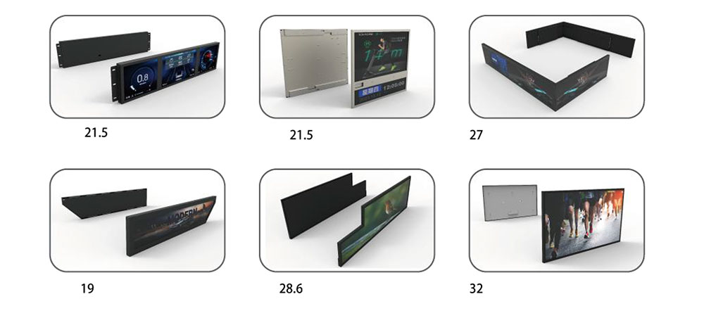
The Legacy Display Problem in British Plant
British industrial equipment is unusually long-lived. A CNC machining centre installed in Coventry in 1998, a fuel-dispensing console on a forecourt in Leeds, a Marconi-era test set still in daily use at a calibration house in Hampshire, or a textile line controller in the Midlands will routinely be asked to run for twenty-five or thirty years. The mechanics and the drives usually survive. The display, more often than not, does not.
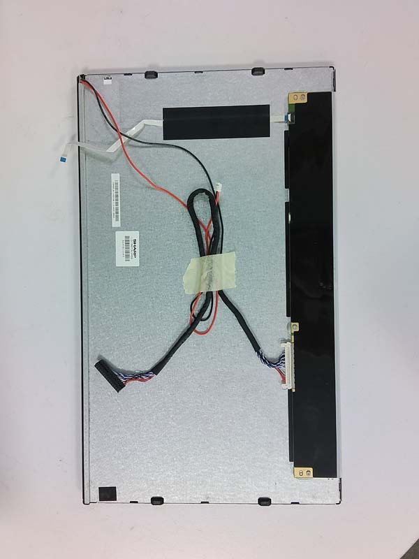
When that display fails, the maintenance engineer faces a specific problem: the original LCD was almost certainly not a standard catalogue part. It was a bespoke panel, a semi-custom module, or a standard glass bonded to a proprietary timing board with a fixed, non-standard resolution and an interface that no distributor now stocks. Fitting a "640×480 VGA module" from a catalogue is not a substitution — it is a redesign, and it usually ends with a stretched image, a missing top menu row, or a controller that refuses to boot because it cannot read the panel's extended display identification data.
This paper sets out how custom resolution LCD replacements are engineered for British industrial systems, and why the LCD Screen RoHS dossier is as important to a successful replacement as the optical performance itself.
Why Pixel Count Alone Is Not the Specification
The single most common cause of a failed LCD replacement is treating resolution as a number of pixels rather than as a set of timing parameters. A legacy display is driven by a source that generates horizontal and vertical sync at a specific pixel clock, with specific front porch, back porch, sync width and polarity values. The panel expects that timing, samples it on a specific edge, and latches data in a specific order. Change the timing and the image does not simply rescale — it jitters, rolls, tears, or disappears.
Four parameters must therefore be captured before any replacement is designed:
- Native format and active area. Not just 320×240, but the exact active area in millimetres, because bezel aperture and mounting geometry are fixed in the host enclosure.
- Pixel clock and sync structure. Including whether the source is interlaced, whether it uses composite sync or sync-on-green, and whether the data is sampled on the rising or falling clock edge.
- Interface electrical standard. 5 V CMOS TTL, 3.3 V TTL, LVDS (single or dual channel), RSDS, TMDS, or a proprietary serial link, together with connector type and pinout.
- Control channel behaviour. Whether the host polls an EDID EEPROM, expects a DDC response, sends an I²C command sequence, or simply powers up and expects a valid signal within a fixed timeout window.
A replacement that satisfies all four is invisible to the host. A replacement that satisfies three is a support call.
Common Legacy Formats and Their Substitution Strategies
| Legacy format | Typical British equipment | Replacement strategy |
|---|---|---|
| 240×64, 240×128 monochrome STN | Test and measurement instruments, analysers, older weighing terminals | Direct 1:1 module, or FPGA timing engine driving a small TFT with pixel doubling and monochrome-to-colour remap |
| 320×240 QVGA | Machine tool pendants, POS terminals, pump controllers | Native 320×240 TFT, or integer 2× scaling to 640×480 to preserve sharp edges |
| 400×240 and 480×272 | Handheld instruments, portable test gear, rail cab displays | Frame-store timing regeneration; fractional scaling with nearest-neighbour on text layers |
| 512×256, 640×256 and other bespoke formats | Bespoke British instrumentation and defence-adjacent ground support equipment | Custom FPGA timing controller with on-board frame buffer; no off-the-shelf equivalent exists |
| 640×480 VGA | PLC operator panels, SCADA terminals, laboratory instruments | Native 640×480 where still available; otherwise 800×480 with configured letterboxing |
| 800×480 WVGA | Mid-2000s operator interfaces and access control | Broad native supply, but pinout and EDID must be matched, not assumed |
| 1024×768 XGA 4:3 | Control-room consoles, medical and analytical instruments | Native 4:3 panel essential; 5:4 substitution distorts and is not acceptable in regulated environments |
Where a native panel no longer exists, the resolution becomes a firmware problem. An FPGA-based timing controller with an integrated frame buffer can accept the legacy source exactly as it is and generate the panel's own timing independently — decoupling source from sink. This is the only approach that works reliably for the bespoke formats, and it also allows the replacement to present a correctly programmed EDID so that hosts which interrogate the display continue to enumerate it without a reconfiguration.
Scaling Quality: The Difference Between Working and Acceptable
Non-integer scaling is where replacements acquire a reputation for looking wrong. Scaling 640×480 to 800×480 involves a horizontal ratio of 1.25, which produces uneven pixel duplication and visibly ragged vertical strokes on text and single-pixel gridlines. Operators notice this immediately on a trend graph or a bar-code readout.
Three techniques mitigate it. First, integer scaling wherever geometry allows: 320×240 to 640×480 is exact and should always be preferred over a fractional path. Second, content-aware handling — bilinear interpolation for photographic or video content, nearest-neighbour for text and line graphics, selectable per installation. Third, honest letterboxing or pillarboxing with a defined background colour, which preserves pixel integrity and is generally preferred by control-room operators over a distorted full-screen image.
Mechanical Fit, Optics and the Backlight Transition
A replacement module is a mechanical part as much as an electronic one. Mounting boss positions, thread size, panel thickness, bezel aperture, connector exit direction and cable bend radius all constrain the design. Where the original used a CCFL backlight with an inverter, the replacement should move to an LED backlight — not merely for longevity, but because removing the inverter removes a high-voltage assembly from inside the enclosure, which is a genuine maintenance-safety improvement and simplifies the electrical safety case.
Optical matching matters equally. Legacy panels were often dim by modern standards, with modest contrast and narrow viewing angles. Dropping in a 1000 cd/m² modern TFT can blind an operator in a dimly lit control room, while an unmodified consumer-grade panel will disappear entirely on a sunlit forecourt or beside a furnace. Brightness should be specified against the actual ambient, not against the catalogue, and PWM dimming frequency must be chosen to avoid beating against camera-based inspection systems and to stay above the flicker-perception threshold.
Environmental specification for British installations typically means −20 °C to +70 °C operation, resistance to condensation in unheated cabinets, and, for marine, offshore and washdown applications, conformal coating and sealed front assemblies to the relevant IP rating under BS EN 60529.
The LCD Screen RoHS Dossier: Compliance That Survives Audit
Substituting a display changes the bill of materials of the host machine, and in the UK that carries legal weight. The Restriction of the Use of Certain Hazardous Substances in Electrical and Electronic Equipment Regulations 2012, as amended, mirror the EU RoHS Directive's ten restricted substances at homogeneous-material level: lead, mercury, hexavalent chromium and cadmium, polybrominated biphenyls and polybrominated diphenyl ethers, plus the four phthalates DEHP, BBP, DBP and DIBP added for most equipment from 22 July 2019.
For an LCD replacement, an LCD Screen RoHS claim is not a statement about the finished module. It is a claim about every homogeneous material inside it: the glass substrate, the indium tin oxide layer, the polariser adhesive, the liquid crystal mixture, the colour filter resin, the driver IC encapsulant, the flexible printed circuit, the solder alloy, the lead-frame plating, the LED phosphor, the diffuser, the light guide, the gasket and the adhesive tape. Each must sit below the threshold — 0.1 % by weight except cadmium at 0.01 % — or be covered by a valid Annex III or Annex IV exemption.
Three points are frequently mishandled:
- Exemptions have expiry dates. The mercury exemption that historically covered CCFL backlights has lapsed for most display applications, which is one reason CCFL-to-LED conversion is now the default path rather than an upgrade. Claims that rely on an expired exemption are not compliance.
- Exemptions are narrow. Lead in glass and ceramic, and lead in high-melting-temperature solders, remain exempt in specific defined uses. A supplier that applies a general "exempt" flag to an entire assembly is not providing a defensible declaration.
- Documentation is the deliverable. A compliant module without a compliant dossier fails audit. The expected package is a full material declaration at homogeneous level in IPC-1752A Class D format, supported by test data generated to the IEC 62321 series — typically XRF screening for the bulk elements, confirmed by ICP-OES or ICP-MS where screening is inconclusive, and by specific wet chemistry for hexavalent chromium and for the phthalates.
| Document | Purpose in a UK substitution project |
|---|---|
| Full material declaration, IPC-1752A Class D | Homogeneous-level substance roll-up; the primary evidence that the module meets the thresholds |
| IEC 62321 series test reports | Independent analytical confirmation, per homogeneous material |
| Technical documentation to BS EN IEC 63000 | Harmonised route for RoHS technical file compilation and retention |
| REACH SVHC declaration and Article 33 communication | Separate obligation from RoHS and just as auditable |
| Manufacturing process statement | Lead-free solder alloy, surface finish (ENIG or immersion tin), no-clean flux, and tin-whisker mitigation via nickel underplate or SnAgCu |
Because the UK and EU regimes now run in parallel, a replacement destined for British plant should carry CE marking with a UKCA route where the operator's own conformity assessment requires it, and the declaration should name the exact module revision — not a family — so that a later component change does not silently invalidate the file.
EMC, Functional Safety and Installation Context
An LCD module is a switching circuit with a fast parallel bus, a boost converter and a PWM driver, installed inside an enclosure that was never designed around it. Emission and immunity should be considered from the outset: BS EN 61000-6-2 and BS EN 61000-6-4 for generic industrial environments, BS EN 61010 for measurement and laboratory equipment, BS EN 60204-1 where the display sits within a machine's electrical equipment, EN 50155 for rail-borne applications, and the BS EN IEC 60079 series where the host is in a classified hazardous area such as a forecourt or petrochemical site.
None of this is beyond a well-designed module, but all of it fails if the replacement is treated as a plug-and-play swap. Ribbon cables routed alongside drive cables, unshielded backlight leads, and grounds bonded at the wrong single point will generate failures that are then blamed on the panel.
Qualification Before Dispatch
A custom resolution replacement should leave the factory with evidence, not assurances. A practical qualification set for industrial duty includes: a thermal soak from cold start at the lower limit through to stabilised operation at the upper limit, with brightness and contrast measured at both; a power-cycle and inrush test against the host's supply; a vibration sweep representative of machine-mounted or vehicle-mounted service; an EMC pre-scan of the assembled module; a continuous burn-in of at least 168 hours with the host's actual signal applied; and a timing capture confirming that the module's output matches the captured original waveforms within agreed tolerances.
Where touch is involved, the overlay must be matched as carefully as the display — a four-wire resistive panel with the same active area and controller protocol for legacy systems, or a projected-capacitive overlay with a USB or I²C bridge where the host software can be updated.
Lifecycle, Traceability and Long-Term Supply
The replacement is only useful if it can be repeated. Good practice is to lock the design on a documented panel source, hold the FPGA configuration and EDID image under revision control, retain golden samples of both the original and the replacement, and require product change notification before any component, adhesive, LED bin or PCB finish is altered. Batch-level traceability — serial number to material declaration to test record — turns a future audit from an investigation into a lookup.
For the maintenance engineer, the practical checklist is short: capture the timing and the interface before removing the old unit; record the active area and mounting geometry; specify brightness against the real ambient; require a homogeneous-level LCD Screen RoHS declaration with current exemptions cited; and insist on qualification data with the shipment. Done that way, a custom resolution LCD replacement restores a British industrial system to full service without asking the host controller to change a single line of its firmware.
KEYWORDS: custom resolution LCD, industrial LCD replacement, legacy display obsolescence, RoHS compliant LCD module, LCD timing controller