Ask a UK instrument designer what constrains their next enclosure and the answer is rarely the processor, the battery or the radio. It is almost always the glass. A handheld analyser, a rail cab repeater, a helmet-mounted sighting unit, a 1U rack-mounted network probe or a subsea valve controller all share the same brutal arithmetic: the front face is fixed by ergonomics, rack width, connector clearance or legacy chassis, and the display has to fit inside what remains. When the only panels on the shelf are 16:9, 4:3 and the occasional 5:4, that leftover rectangle almost never lands on a catalogue ratio. This is the point at which a custom aspect ratio stopgap becomes the difference between a product that ships and one that spends another year in mechanical rework.
Why the Panel Envelope, Not the Pixel Count, Drives the Design
Most display sourcing conversations start with resolution. They should start with the aperture. In a space-constrained product, three numbers decide everything before anyone discusses a driver IC: the active area (the illuminated region), the outline dimension (the glass plus any bezel), and the thickness of the full stack behind the glass. A 10.1” 16:9 panel has an active area of roughly 217 × 136 mm. If your enclosure provides 200 × 140 mm of window, no amount of firmware cleverness will make that panel fit. If it provides 170 × 150 mm, you are looking at a genuinely non-standard geometry — probably close to 17:15 — and that shape has to be manufactured, not selected.
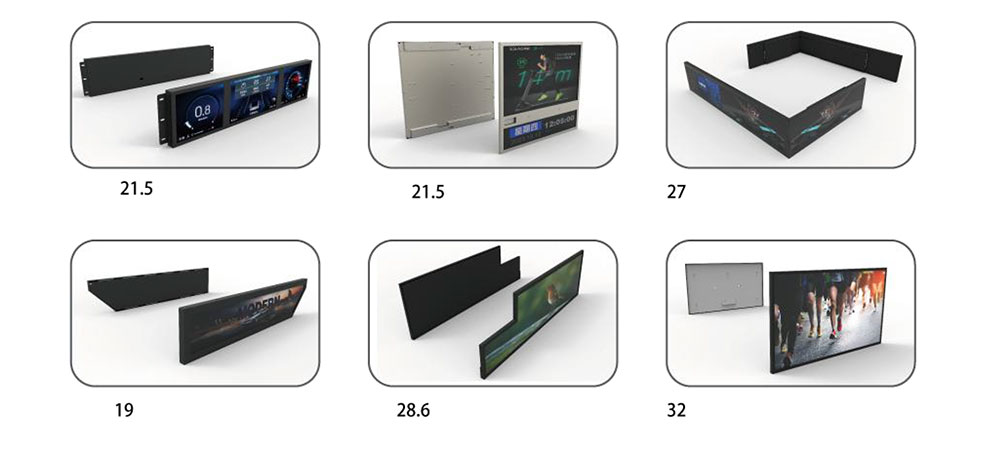
The commercial consequence is straightforward: standard panels are cheap because mother glass is cut into thousands of identical cells. Deviate from those cells and you leave the volume economy of the panel maker. The engineering consequence is equally straightforward: you gain exact control over mechanical fit, interface position, connector orientation, brightness and operating temperature, all in one part number that will not be discontinued by a consumer roadmap three quarters from now. For low- and mid-volume British equipment builders — the 200 to 20,000 unit per year bracket that dominates defence, rail, medical, energy and test-and-measurement — that trade is usually worth making.
A Practical Taxonomy of Custom Aspect Ratio Work
“Custom” covers a wide spectrum, and knowing where your requirement sits determines cost, lead time and risk.
- Tier 1 — Respin of a standard cell. Same active area, same ratio, but custom FPC length, connector position and pinout, altered backlight current, wider temperature grade. Lowest NRE, shortest lead time, no new tooling.
- Tier 2 — Standard cell, cut outline. The active area is unchanged, but the glass is trimmed, the bezel removed on one or more edges, cover glass bonded directly, and the outline reduced asymmetrically. Ideal for “edge-to-edge on three sides” requirements.
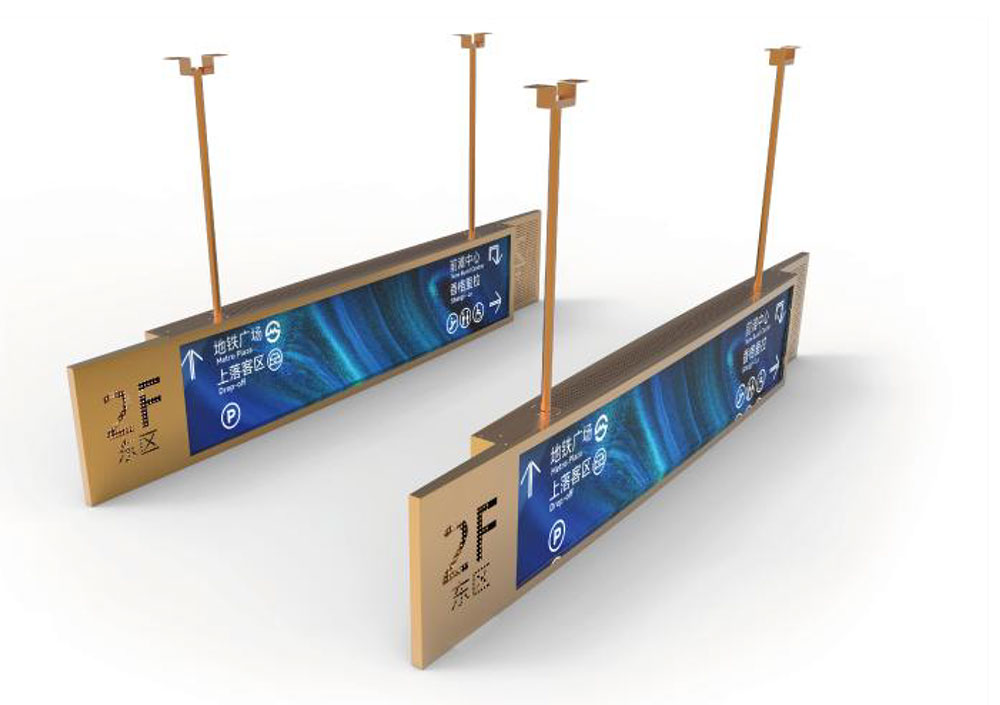
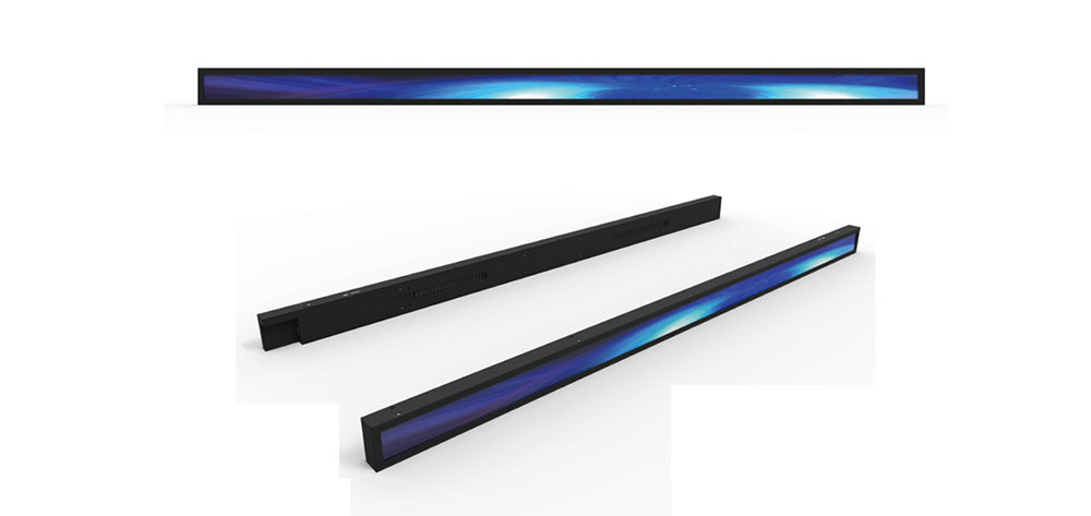
- Tier 3 — New aspect ratio from an existing cell family. A cell design is reused but re-masked for a different ratio: 16:10.5, 3:2, 5:4, 1:1, 8:3 ultrawide bars, 2.8:1 letterbox formats, tall portrait strips. Moderate NRE, real tooling, 14–20 weeks to first samples typical.
- Tier 4 — Fully bespoke geometry. Asymmetric aspect ratios, cut corners, notches, circular or rounded active areas, non-rectangular apertures, mixed portrait/landscape in one chassis. Highest NRE, longest schedule, but the only route when the enclosure is genuinely immovable.
Reading the Geometry Properly: Active Area, Outline and Pixel Pitch
Pixel pitch is your first sanity check: pitch = active width ÷ horizontal pixel count. A 1920 × 720 bar display with a 260 mm active width has a 0.135 mm pitch, which is fine for a metre-and-a-half viewing distance and hopeless at 300 mm. Conversely, a 1024 × 768 panel squeezed into a 170 mm width gives a 0.166 mm pitch and a comfortable HMI at arm's length. Because a custom ratio lets you trade resolution against physical size independently, you can arrive at a legible pitch without changing the enclosure — something a fixed catalogue ratio cannot offer.
Beware the difference between the active area tolerance and the outline tolerance. Active area is defined by the mask and is tight, typically ±0.2 to ±0.5 mm. The outline, especially on cut glass, is looser — often ±0.3 to ±1.0 mm — and the mechanical designer must reference the active area, not the glass edge, when locating the aperture. Getting this wrong produces a bezel that looks proud on one side and flush on the other, or worse, clips the first and last pixel columns.
Where UK Equipment Actually Breaks the Standard Grid
Certain sectors in the UK generate the same non-standard requests year after year, and the pattern is worth understanding because it tells you what a display partner should already have on file.
- 19-inch rack systems. A 1U or 2U rack faceplate rarely accommodates a 16:9 panel without wasted vertical space. Ultrawide bars around 8:3 or 3:1 suit rack monitoring; near-square formats around 5:4 suit control panels where operators need vertical field lists.
- Rail and roadside. Cab displays and trackside equipment frequently need portrait strips or 4:3 at high brightness, with wide temperature and vibration requirements driven by BS EN 50155 and BS EN 50121-3-2.
- Handheld and body-worn instruments. The window is dictated by grip and glove use, not by panel availability. Ratios in the 1.4–1.7 range appear constantly, together with sub-2 mm overall thickness and bonded cover glass.
- Medical and laboratory devices. Cart-mounted monitors, pump front panels and analyser windows often want square or near-square displays so that numerical readouts and waveform panels coexist without wasted area.
- Marine, offshore and subsea. North Sea and offshore wind operators specify salt-mist resistance, condensation tolerance and enclosure sealing that no standard panel provides out of the box; the geometry is often driven by existing console cut-outs from 1990s equipment.
- Defence and aerospace. Legacy chassis retrofit is the dominant driver. When replacing a CRT or an obsolescent electroluminescent display, the aperture is fixed and the new panel must match exactly, regardless of pixel format.
The Mechanical Stack: What Actually Consumes the Millimetres
Designers routinely under-budget the depth behind the glass. A realistic accounting for a mid-size high-brightness module runs as follows:
| Element | Typical thickness | Notes |
|---|---|---|
| Cover glass or PC window | 1.0–3.0 mm | Chemically strengthened or polycarbonate; thicker glass with a PCAP touch adds mass and stiffness |
| Bonding layer (OCA or LOCA) | 0.15–0.5 mm | Liquid optically clear resin tolerates curved or thick cover glass better than tape |
| Touch sensor (if present) | 0.4–1.1 mm | Glass-on-glass or film-on-glass; film stacks save depth and weight |
| LCD cell | 0.6–1.4 mm | Two glass substrates plus liquid crystal gap |
| Optical films | 0.3–0.8 mm | Diffusers, prism sheets, reflective polariser for brightness gain |
| Light guide plate | 1.0–4.0 mm | Thicker LGP increases uniformity and permits a wider LED pitch; thinner LGP forces more LEDs and more heat |
| Reflector and rear frame | 0.5–1.5 mm | Often doubles as the thermal path to the chassis |
| FPC bend and connector | 3–8 mm | Bend radius is typically 3–5 × FPC thickness; a ZIF connector adds 3–5 mm of local clearance |
Two lessons follow. First, optical bonding is not merely a contrast improvement — it removes the air gap that otherwise traps moisture and lets light bounce between layers, and it mechanically stiffens the stack so thinner cover glass survives impact. Second, the FPC is a mechanical component. A custom module lets you specify its exit edge, its length, its bend direction and its connector orientation, which can save 10 mm or more of internal depth compared with an off-the-shelf flex.
Brightness Without Anywhere to Put the Heat
High brightness and tight space are in direct conflict. Delivering 1,000 cd/m² from a 250 cd/m² baseline typically means roughly a fourfold increase in backlight power; a 10-inch panel can move from 2 W to 8 W or more. In an open chassis that is trivial. In a sealed IP65 enclosure with no convection, it is a thermal design problem that must be solved in the display itself.
Practical countermeasures include: a light guide thickness and LED pitch chosen so that junction temperature stays inside the derating curve at maximum ambient; LED binning that accounts for forward-voltage spread so that series strings do not force a higher rail; a metal-core or aluminium rear frame that lands on a chassis boss with a thermal pad rather than an air gap; and a driver architecture that supports thermal foldback, reducing current gracefully above a measured threshold instead of shutting down. Where the enclosure has any surface exposed to airflow, conduct heat to it — display manufacturers should be able to model this and share the thermal resistance figures rather than quoting a single “maximum ambient” number.
Interfaces in a Narrow FPC
Bandwidth and aspect ratio are linked. A wider format at the same height means more horizontal pixels and therefore more data. A 1920 × 720 bar panel carries about 40 percent more pixels than 1280 × 720, which is the difference between comfortable single-channel LVDS and a marginal one. As a rule, plan for the following:
- Parallel RGB (24-bit TTL): simple, cheap, but limited to roughly 1280 × 800 at 60 Hz and it consumes around 30 signal lines, which crowds an FPC.KEYWORDS: Custom Aspect Ratio LCD Displays for Space-Constrained Equipment in the UK