Introduction
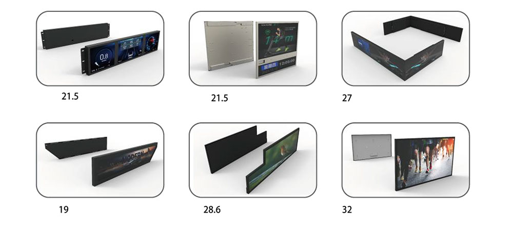
Industrial equipment rarely offers a neat rectangular window for a standard display. Rack-mount instruments, shelf-edge controllers, elevator panels, factory-line indicators, and diagnostic terminals often present long, narrow, or awkwardly proportioned openings. A conventional 4:3 or 16:9 panel forces designers to either waste mounting space or redesign the enclosure. Stretched LCD displays solve this by delivering ultra-wide or ultra-tall active areas that map directly to the mechanical envelope. When paired with a custom Flexible Printed Circuit (FPC), the result is a display that fits the equipment, routes signals cleanly through tight interiors, and survives the mechanical and thermal stress of an industrial environment.
At HITULCD, we engineer high-brightness stretched LCD modules with custom FPC designs tailored to the host system. This white paper explains the technology, the design considerations for the FPC interface, and the specification ranges that matter when integrating these displays into industrial equipment.
What Is a Stretched LCD Display?
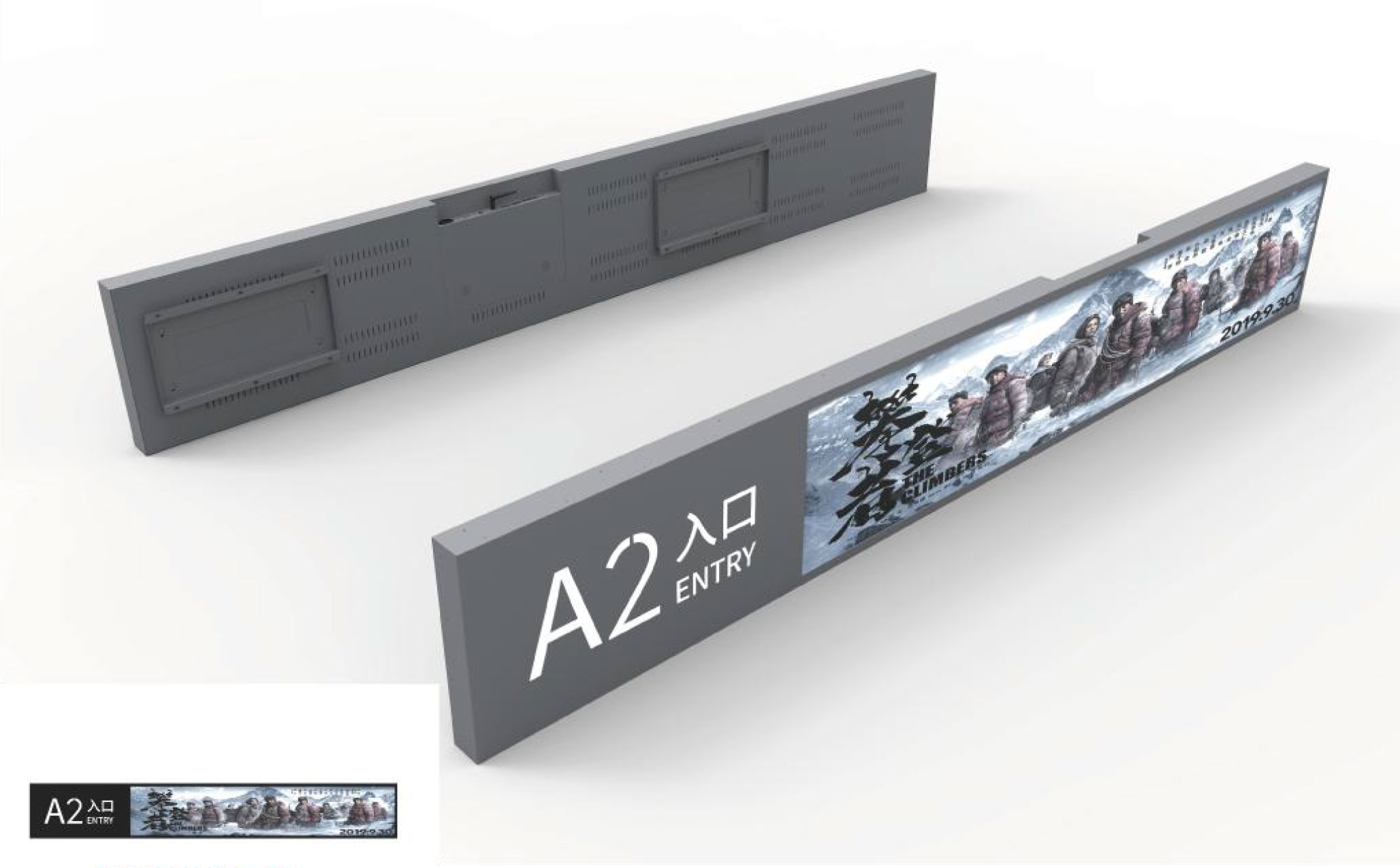
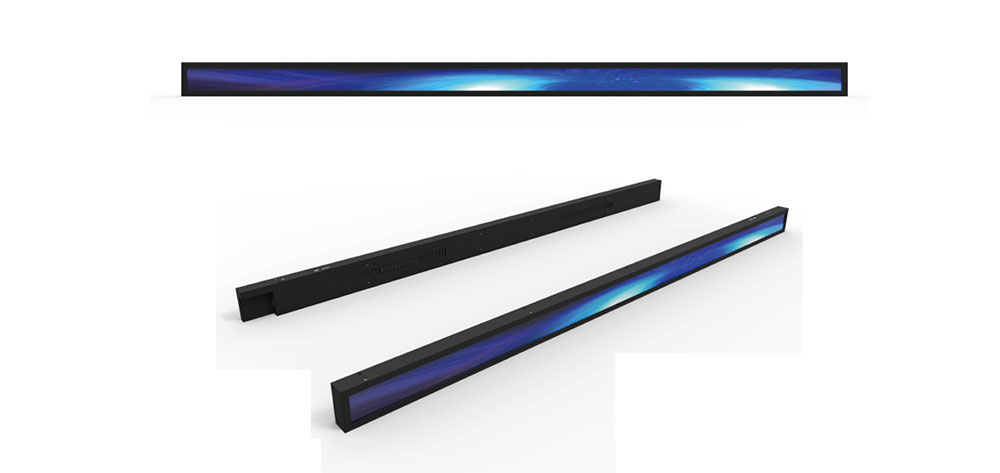
A stretched (or "bar-type") LCD is a panel whose aspect ratio departs sharply from consumer norms. Aspect ratios such as 16:3, 16:4.5, or 4:1 are common, producing long, thin viewing areas ideal for status bars, sequence readouts, and edge-of-shelf signage. There are two manufacturing routes:
- Cut (or "bar-cut") panels — a full-size mother glass is cut down to the target ratio, with the driver architecture reworked to address the reduced active area. This is the most cost-effective route for standard bar ratios.
- Purpose-built stretched panels — the glass and TFT array are designed from the outset for the target dimensions, allowing tighter borders and optimized driver placement.
For industrial use, brightness, temperature tolerance, and interface flexibility usually matter more than the last millimeter of border width, so cut panels with reinforced backlights and custom FPCs are a frequent and economical choice.
Why the FPC Matters
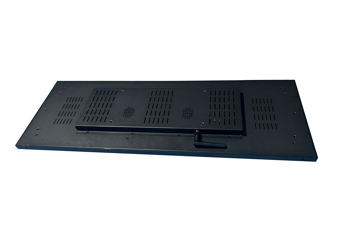
The Flexible Printed Circuit is the ribbon that carries display data, timing, backlight power, and touch signals between the panel and the host board. In a standard off-the-shelf module the FPC is fixed in length, exit direction, and connector type. Inside real industrial equipment those defaults rarely line up with the mainboard location, and forcing a fit means sharp bends, tension on solder joints, and long-term reliability risk.
A custom FPC lets us control:
- Length and routing path — the ribbon reaches the host connector without excess slack or strain.
- Exit direction and bend geometry — top, bottom, or side exit with a defined minimum bend radius.
- Connector and pin-out — matching the customer's board-to-board or ZIF connector and signal order.
- Integrated components — placement of the backlight driver, EMI shielding, or a stiffener at the connector.
- Interface conversion — carrying RGB, LVDS, MIPI-DSI, or SPI, and hosting a bridge IC where a protocol change is needed.
Typical Specification Ranges
The table below shows the parameter ranges we typically work within for custom FPC stretched LCD modules aimed at industrial equipment. Exact values depend on the panel size and application.
| Parameter | Typical Range | Notes |
|---|---|---|
| Diagonal size | 8" to 38" | Larger custom sizes available on request |
| Aspect ratio | 16:3 to 4:1 | Bar-type / ultra-wide |
| Brightness | 500 to 2500 cd/m² | High-bright options for outdoor / sunlight-readable use |
| Contrast ratio | 800:1 to 1500:1 | Panel dependent |
| Viewing angle | Up to 89°/89°/89°/89° (IPS) | Wide-angle for shelf-edge and overhead mounting |
| Operating temperature | -30°C to +85°C | Wide-temp grade with heater option below -20°C |
| Storage temperature | -40°C to +90°C | |
| Interface | LVDS, MIPI-DSI, RGB, SPI | Selected per resolution and cable length |
| Backlight lifetime | 50,000 h (typ.) | To half initial brightness at 25°C |
| FPC bend radius (min.) | ≥ 3 mm | Depends on copper thickness and layer count |
These figures are representative ranges, not guaranteed values for any single model; final specifications are confirmed against the chosen panel and drive conditions.
Interface Selection Guide
Choosing the right interface early avoids costly redesign. The table summarizes the practical trade-offs.
| Interface | Best for | Practical cable length | Consideration |
|---|---|---|---|
| SPI | Small panels, low resolution | Short | Low pin count, low bandwidth |
| RGB (parallel) | Mid resolution, short runs | Short | Many signal lines, EMI sensitive |
| MIPI-DSI | High resolution, compact routing | Short to medium | Differential, low EMI, needs compatible SoC |
| LVDS | Larger panels, longer runs | Medium to long | Robust, common in industrial mainboards |
Mechanical and Environmental Design
Industrial equipment subjects the display to vibration, thermal cycling, dust, and sometimes moisture. A custom FPC stretched module is designed with these in mind:
- Strain relief — a stiffener at the FPC-to-connector junction prevents solder-joint fatigue under vibration.
- Optical bonding — filling the air gap between cover glass and panel improves sunlight readability, reduces internal condensation risk, and increases impact resistance.
- Wide-temperature tuning — liquid-crystal fluid selection and, where needed, a film or wire heater keep response time acceptable in cold starts.
- EMI control — grounded shielding on the FPC and controlled-impedance traces keep emissions within the limits industrial equipment must meet.
Brightness and Readability
Many industrial displays sit under strong overhead lighting or near windows. Brightness alone is not the full story; ambient contrast ratio is what the operator actually perceives. High-brightness backlights (1000 cd/m² and above) combined with optical bonding and an anti-glare or anti-reflective cover glass deliver readable content where a standard 250–350 cd/m² office panel would wash out. For always-on equipment, an ambient light sensor driving automatic dimming both preserves readability and extends backlight life.
Design and Integration Workflow
A custom FPC project moves through a defined sequence to control risk and lead time:
- Requirement capture — active area, brightness, temperature grade, interface, and connector location.
- Mechanical envelope review — 2D/3D of the enclosure to define FPC length, exit, and bend path.
- Electrical definition — pin-out mapping, backlight drive method, and any bridge IC.
- Sample build — engineering samples with the custom FPC for fit and functional check.
- Reliability testing — thermal cycling, vibration, and flex-life verification of the FPC.
- Production release — locked drawings and traveler for repeatable manufacturing.
Application Examples
- Factory line status bars — ultra-wide readouts showing throughput, alarms, and cycle state above conveyor sections.
- Rack instruments — thin displays fitting the front panel of test and measurement gear.
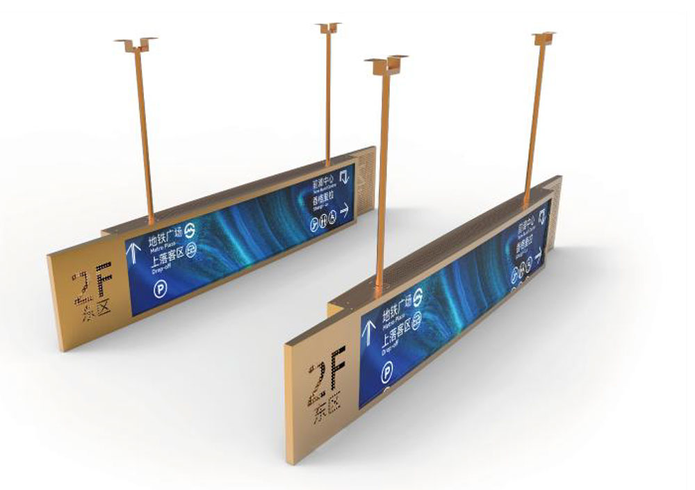
- Access and elevator panels — tall or wide bars for floor indication and messaging.
- Vending and kiosk controllers — shelf-edge and side-strip information displays.
- Energy and process control — wide dashboards summarizing multiple channels at a glance.
Conclusion
A custom FPC stretched LCD display turns an awkward mechanical opening into a clean, readable, and reliable operator interface. By matching the active area to the equipment, routing the FPC to the host board without strain, and specifying brightness and temperature grades to the real operating environment, integrators avoid enclosure compromises and field failures alike. HITULCD supports this end to end, from bar-type panel selection through custom FPC design, optical bonding, and reliability validation, so the display fits both the housing and the working life of the equipment.
KEYWORDS: custom FPC stretched LCD, industrial LCD display, high-brightness bar-type LCD, stretched LCD for industrial equipment, custom LCD module