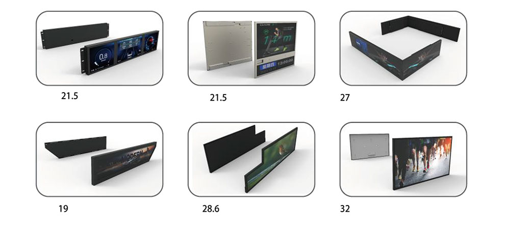
Why Bar Type LCDs Become Obsolete Long Before the Equipment Does
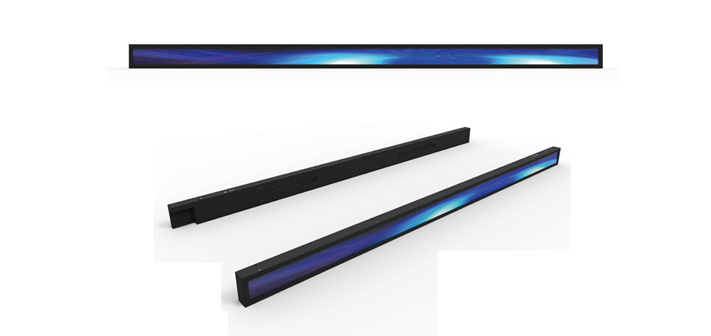
A bar type LCD — the shallow, wide-format panel typically built at geometries such as 240×64, 256×64, 320×96 or 480×128 pixels — sits inside a category of equipment that is expected to run for fifteen to twenty-five years: benchtop analysers, rack-mounted signal generators, patient monitors, audio and broadcast units, industrial weighbridges, vending and ticketing terminals, laboratory centrifuges and legacy point-of-sale hardware. The panel itself rarely fails on that timescale, but the supply chain behind it does. Once a fab closes a low-volume STN or FSTN line, once a controller IC such as the T6963C, SED1335, HD61830 or RA8835 goes end-of-life, once the CCFL inverter supplier stops producing the matching transformer, the display becomes unrecoverable through normal channels — and the host instrument, still fully functional and often still calibrated, becomes scrap.
Replacing that display is a legitimate engineering project, not a parts-sourcing exercise. It involves reverse-engineering an undocumented interface, re-qualifying the mechanical envelope, sometimes rewriting the display driver layer, and — critically — proving through documented testing that the replacement does not degrade the equipment's safety, EMC performance or measurement accuracy. This paper sets out a repeatable method for that work, with the test evidence that should accompany each stage.
Stage 1 — Establish the Asset Baseline Before Touching the Unit
Every replacement project should begin with a documented survey of the equipment as found. That record becomes the reference against which the finished modification is judged, and it is the first item in the technical file.
- Record the host instrument's make, model, serial number, firmware revision and asset number.
- Photograph the display in situ from the front, the side and the rear, including the flex tail routing and any adhesive or gasket material.
- Capture every screen the instrument can display, using a camera on a tripod with fixed exposure. Menus, setup pages, error codes and calibration screens are all part of the functional specification of the replacement.
- Measure the visible aperture, the bezel opening, the panel outline, thickness, mounting boss positions and the distance from the front glass to the host PCB.
- Record the ambient operating temperature range stated on the instrument's rating plate and the environment in which it actually runs.
This baseline is not bureaucracy. Where a replacement is later challenged — by a customer, an insurer, a calibration body or a notified body — the comparison between "as found" and "as modified" is what demonstrates that nothing was lost.
Stage 2 — Reverse-Engineer the Electrical Interface
Obsolete bar displays connect to the host in one of four ways, and identifying which is in use determines the entire replacement strategy.
| Interface type | Typical signals | Identification clues | Replacement implications |
|---|---|---|---|
| Parallel MPU bus (8080/6800) | D0–D7, /WR, /RD, A0/RS, /CS, /RES | 8 or 16 conductors on the tail; controller IC visible on the panel | Direct controller-compatible swap possible if resolution matches |
| Serial SPI | SCLK, MOSI, /CS, A0, /RES | 4–6 conductors; high clock rate on a scope | Requires protocol translation or firmware change |
| RGB / LVDS TTL | Pixel clock, HSYNC, VSYNC, DE, R/G/B | 20+ conductors; continuous clock even when idle | Needs a timing-matched panel or a bridge board |
| Smart / serial command module | TX, RX, /BUSY | 2–3 conductors; ASCII traffic | Easiest path — emulate the command set |
Capture the bus with a logic analyser at the instrument's real operating speed, not a guessed nominal one. Record setup and hold times, chip-select pulse widths, reset duration and the initialisation byte sequence written at power-up. That power-up sequence is the single most valuable capture in the project: it tells you the bias settings, the duty ratio, the scan direction and the display RAM addressing mode that the firmware expects, and it is the reference against which any replacement controller must be configured.
Document the logic levels explicitly. Many 1990s and early-2000s designs run the display bus at 5 V while the host microcontroller core is 3.3 V; a modern replacement panel is almost always 3.3 V or lower and will need level shifting on every input, including the reset and chip-select lines. Feeding 5 V logic into a 3.3 V panel is a reliable way to destroy it during commissioning, and a documented interface schedule prevents that error from being repeated by a second engineer.
Stage 3 — Choose the Replacement Path
There are three viable routes, and the right one depends on how much firmware access the project allows.
Route A — Controller-compatible drop-in
Where the host uses a parallel bus and the firmware drives a known controller family, a panel built around the same or a register-compatible controller can be fitted without any software change. This is the lowest-risk option and the only one that avoids re-validating the instrument's firmware. Availability is the constraint: register-compatible bar-format TFT modules in small quantities are increasingly sourced from specialist suppliers who build to order rather than from catalogue distribution, so lead time must be planned at the outset.
Route B — Controller substitution with a translation layer
A small bridge board — either a CPLD/FPGA or a microcontroller with a fast parallel port — accepts the legacy bus traffic and re-renders it onto a modern TFT with a different native resolution. The translation layer converts the legacy display RAM map into the new panel's frame buffer, which means font tables, cursor positions and any graphics primitives must be re-mapped. This route preserves the host firmware untouched, which is often the deciding factor for equipment whose source code no longer exists or whose build toolchain cannot be reproduced.
Route C — Firmware modification
Where source code and a reproducible toolchain are available, the cleanest long-term answer is to retarget the display driver to a currently produced module. It is also the route that carries the heaviest validation burden, because the change touches the same binary that performs measurement and control. Regression testing of the whole instrument, not just the display, becomes mandatory.
Regardless of route, select the replacement for the environment rather than the bench. High-brightness transmissive TFT modules with 800–1000 cd/m² output and wide operating temperature ranges are the sensible default for equipment installed in unlit plant rooms, outdoor kiosks or factory floors, where the original STN panel's 80–150 cd/m² was only ever adequate under office lighting.
Stage 4 — Mechanical and Optical Integration
The replacement will not match the original outline. Plan for an adapter rather than forcing the panel into the old aperture.
- Machine or 3D-print a carrier frame that locates the new panel on the original mounting bosses and presents the correct front-face datum.
- Match the visible aperture to the new active area and mask any remainder with a bezel of the same colour and gloss level as the original, so the modification is not visually obvious.
- Retain or replace the environmental seal. If the host carries an IP rating, the seal is part of that rating and must be re-tested, not assumed.
- Check the front glass thickness and any anti-glare or anti-reflective treatment against the original; a change here alters legibility under the lighting conditions the equipment was designed for.
- Verify that the flex tail or FPC does not foul the host PCB or the enclosure door, and strain-relieve it.
Stage 5 — Power and Backlight
Legacy bar displays used CCFL tubes with a separate inverter, or electroluminescent (EL) foil with a high-frequency inverter. Both introduce high voltages into the assembly and both are failure points. LED backlit replacements remove the inverter entirely, which is a safety improvement but requires the host's backlight supply to be re-examined: the original inverter input may be a poorly regulated 5 V or 12 V rail with significant ripple, and the new LED driver needs a clean supply and a defined dimming method (PWM, analogue or resistor-set).
Record the new module's inrush current and continuous consumption against the host's available headroom. A replacement that draws more than the original inverter can push an already-marginal linear regulator into thermal shutdown, particularly inside a sealed enclosure running at 40 °C ambient.
Stage 6 — UK Regulatory Position
Work of this kind is a modification to equipment already placed on the UK market, and the compliance route depends on how the modified unit is treated.
- Safety: benchtop and laboratory instruments are typically assessed to BS EN 61010-1; IT and AV equipment to BS EN 62368-1. Any change to the mains-side assembly, including inverter removal, requires re-checking of creepage, clearance, dielectric strength and touch temperature.
- EMC: emissions to BS EN 55032 or the relevant product family standard (BS EN 61326-1 for measurement equipment), immunity to the IEC 61000-4 series. A new switching LED driver and a faster pixel clock both change the emissions profile.
- Substances and waste: UK RoHS and WEEE obligations apply to the replacement module and to the removed parts; retain supplier declarations in the technical file.
- Work equipment: where the host is used as work equipment, PUWER requires that it remains safe and suitable for use after modification — which is a documentary requirement as much as an engineering one.
Where the modification is carried out on the owner's own equipment as maintenance, a full conformity assessment is not normally required, but the engineering evidence below is what demonstrates due diligence if an incident occurs.
Stage 7 — The Documented Test Programme
This is where most retrofit projects fail commercially: the display works on the bench, and there is nothing to show that it works in service. Every claim made about the replacement should be traceable to a numbered test, performed against a written protocol, executed with calibrated instruments and signed by the person who ran it. The table below is a defensible minimum programme for a bar-format LCD replacement in UK industrial or laboratory equipment.
| ID | Test | Method / reference | Acceptance criterion |
|---|---|---|---|
| D-01 | Mechanical fit and aperture alignment | Dimensional check against Stage 1 baseline | No interference; active area centred within ±0.5 mm |
| D-02 | Power-up and initialisation | Logic analyser capture vs recorded legacy sequence | Identical init sequence accepted; no bus contention |
| D-03 | Timing margin | Setup/hold measurement at temperature extremes | ≥ 20 % margin on all host-driven signals |
| D-04 | Luminance and uniformity | Calibrated photometer, 9-point grid | Within ±15 % of declared value; uniformity ≥ 75 % |
| D-05 | Contrast and viewing angle | Photometer at 0°, ±45° horizontal, +20°/−30° vertical | Contrast ≥ 300:1 on axis; readable at all specified angles |
| D-06 | Colour fidelity (where colour used) | Colorimeter against reference patches | ΔE ≤ 5 against the specified palette |
| D-07 | Screen content regression | Photographic comparison of every screen from Stage 1 | All characters, icons and units present and correct |
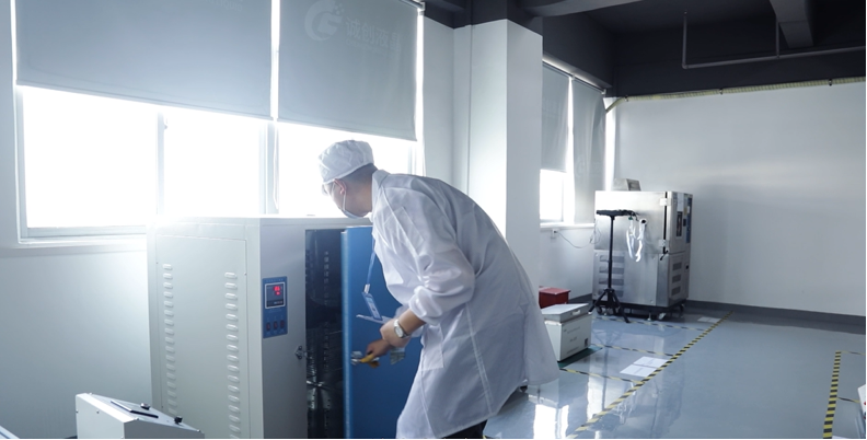
| D-08 | Thermal soak, high | Soak at maximum rated ambient +10 K for 4 h | No flicker, no reset, surface rise ≤ 15 K |
| D-09 | Thermal soak, low | Minimum rated ambient for 4 h, then power-up cold | Correct start-up; response time within spec |
| D-10 | Damp heat | BS EN 60068-2-78, 40 °C / 93 % RH, 48 h | No condensation on active area; function retained |
| D-11 | Vibration and shock | BS EN 60068-2-6 and -2-27, to host rating | No connector, FPC or mounting failure |
| D-12 | ESD immunity | IEC 61000-4-2, contact and air discharge | No permanent degradation or lock-up |
| D-13 | Emissions pre-compliance | BS EN 55032 radiated, 30 MHz–1 GHz | ≥ 6 dB margin to limit |
| D-14 | Safety re-check | Dielectric strength, creepage, touch temperature | Compliant with BS EN 61010-1 or 62368-1 as applicable |
| D-15 | Backlight endurance | 1000 h continuous at rated drive, luminance logged every 100 h | ≥ 90 % of initial luminance retained |
| D-16 | Instrument performance verification | Calibration check against certified reference, before and after | Within the instrument's published tolerance |
Two entries deserve emphasis. D-07 is routinely skipped and is the most common cause of a retrofit being rejected in the field: a font table that renders "µ" as "u" on a laboratory analyser is a functional defect, not a cosmetic one. D-16 is the test that protects the customer's accreditation — for any instrument used in a regulated measurement chain, the display change must be shown not to have disturbed the measurement, and the before-and-after calibration certificate pair is the evidence.
Stage 8 — Records, Traceability and Sign-Off
Each test record should carry the test ID, the date, the equipment under test with serial number, the instrument used with its calibration due date, the raw result, the pass/fail decision, and a signature. Deviations are recorded, not deleted: a documented deviation with a technical justification is evidence of engineering judgement, whereas a missing result is evidence of nothing. The completed package — baseline survey, interface schedule, mechanical drawings, test protocol, test records, calibration certificates, supplier RoHS declarations and photographs — is assembled into a single technical file for the unit and a master file for the modification type.
A 30-day field trial under real operating conditions, with a daily log of any display anomaly, closes the loop. It costs almost nothing and it catches the failures that bench testing cannot: intermittent flex fatigue, condensation in a cold store, sunlight washout at a south-facing kiosk.
Practical Lessons
- Order two replacement modules for every one you need. Small-batch bar-format panels are frequently built to order, and a second unit removes the schedule risk of a single failure during commissioning.
- Photograph and label every connector before disassembly. Legacy assemblies often use friction-fit FPCs with no keying.
- Never rely on the old panel's datasheet being correct — measure the bias and contrast voltages on the working unit before removal, because the host's resistor network is what actually sets them.
- Treat the removed display as hazardous waste if it contains a CCFL tube; mercury-containing lamps fall under WEEE obligations.
- Keep the original firmware image and a copy of the display driver source with the technical file. The next person to open the instrument will need it.
Conclusion
Replacing an obsolete bar type LCD in UK equipment is entirely achievable, and it is usually far cheaper than replacing the instrument — but only when the work is run as a qualification project rather than a soldering job. The sequence matters: baseline the asset, capture the interface, choose the least invasive replacement route, integrate mechanically and electrically with the host's environmental rating in mind, and then prove the result with a numbered, signed, calibrated test programme that covers function, environment, EMC, safety and measurement accuracy. Documented testing is what converts a working prototype into an engineering change that a customer, an auditor or a regulator can accept — and it is the difference between a modification that survives twenty more years in the field and one that comes back on a pallet.
KEYWORDS: bar type LCD replacement, obsolete LCD retrofit UK, industrial LCD upgrade, LCD drop-in replacement testing, high brightness LCD module