Why Stretched LCD Modules Fail, and Why Replacing Them Is Harder Than It Looks
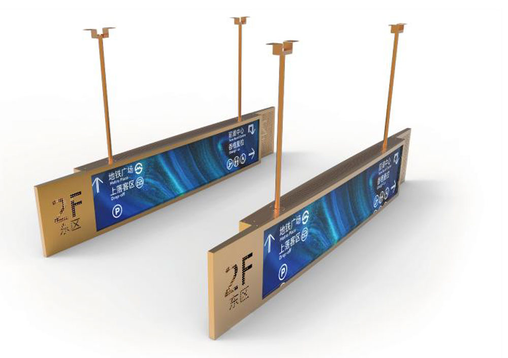
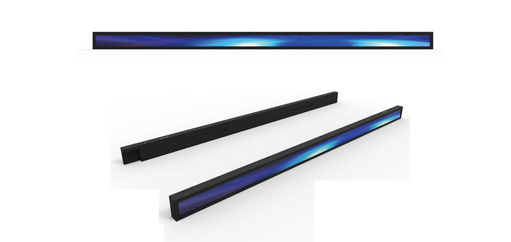
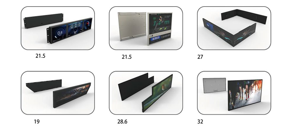
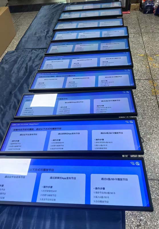
Stretched LCD modules — the long, narrow bar-format displays that sit above shop doors, inside lift cars, along baggage-carousel gantries, and across the fascia of vending and ticketing machines — have become a default design choice for UK original equipment manufacturers (OEMs). Their aspect ratios, typically somewhere between 8:1 and 3:1, let an engineer put a wide strip of information into a mechanical envelope that a 16:9 panel simply cannot fill without wasted bezel and wasted enclosure volume.
The problem arrives five to ten years later. The panel that was designed into that machine goes end-of-life, the tooling that produced the light guide is retired, and the OEM is left holding fielded equipment that still works everywhere except the display. A replacement is needed — and it is rarely as simple as buying "the same size screen."
This article sets out how stretched LCD replacement actually works for UK OEM equipment: what has to match, what can be adapted, what the regulatory obligations are, and how to structure a sourcing and validation programme that does not stall a service line.
What Counts as a "Stretched" LCD Module
A stretched module is a display whose active area is deliberately far from standard consumer geometry. The industry uses a handful of shorthand terms — bar-type, banner, ultra-wide, shelf-edge, and "stretched" — and they overlap. What matters for replacement is not the marketing label but four measurable facts:
- Active area diagonal and aspect ratio (e.g. 16:4.5, 16:3, 3:1, 37:12).
- Outline dimensions and the position of the active area within the outline — asymmetric offset is common and is the single most frequent cause of a "same size" replacement that will not fit.
- Backlight architecture and drive — edge-lit on two long edges, single long edge, or direct-lit; and the number of LED strings and their forward-voltage grouping.
- Signal interface and timing — LVDS, eDP, V-by-One HS, or MIPI DSI, plus lane count, colour depth, and refresh behaviour.
Two modules can share a nominal diagonal and have almost nothing else in common. Any replacement proposal that leads with the diagonal alone should be treated as a starting point, not an answer.
The Compatibility Stack: Six Layers That Decide Whether a Swap Works
A workable replacement programme treats compatibility as six independent layers. A mismatch in any one of them turns a "drop-in" into a project.
1. Mechanical layer
Fixing-hole pitch, thread size, insert depth, screw standoff height, and the flatness tolerance of the mounting plane. OLED and LCD modules also differ in how much of their outline is glass versus metal frame, which affects clamping pressure. Retrofits frequently solve mechanical mismatch with a machined adapter bracket rather than a new enclosure — provided the adapter does not intrude on the viewing aperture or trap heat.
2. Dimensional/optical layer
Active area must align to the existing aperture and, in overlayed designs, to the existing touch sensor or front glass. Bezel widths around the active area must be equal to or smaller than the original, or the visible window changes. Also check the polariser treatment: a replacement with a different surface finish (gloss versus anti-glare) will read as a different product to an end user even if every dimension matches.
3. Electrical layer
Input voltage rails, sequencing, inrush behaviour, and connector family. Bar-format panels often use fine-pitch board-to-board connectors that are not pin-compatible across generations. This is where a small interface adapter board earns its cost: it can re-map pinout, level-shift, and re-sequence, letting an existing host PCB drive a newer panel without a re-spin.
4. Signal/timing layer
Even with identical interface type, the panel's timing parameters — blanking, polarity, lane mapping, and power-on sequence — must match what the host generates. Where they do not, an LVDS or eDP bridge board with an embedded scaler can regenerate the signal from a standard source. This is the most common route for replacing an obsolete proprietary interface.
5. Firmware/EDID layer
Any host that reads EDID, or that stores a backlight curve or gamma table keyed to the original panel, needs that data re-programmed. Budget for this explicitly. A hardware-perfect replacement that boots to a black screen because the host rejects the EDID is a firmware problem, not a panel problem.
6. Environmental layer
Operating temperature range, storage range, humidity, vibration, and — for outdoor or semi-outdoor UK installations — condensation and salt-laden coastal air. A commercial-grade module substituted into an industrial application will pass bench testing and fail in the field. Match the temperature grade first, then everything else.
| Layer | Typical failure point | Common mitigation |
|---|---|---|
| Mechanical | Fixing-hole pitch and standoff height | Machined adapter bracket |
| Dimensional/optical | Active-area offset within outline | Custom outline or offset glass |
| Electrical | Connector family and pinout | Interface adapter board |
| Signal/timing | Obsolete or proprietary interface | LVDS/eDP bridge with scaler |
| Firmware/EDID | Host rejects unknown panel ID | EDID and gamma re-programming |
| Environmental | Temperature or humidity grade | Industrial-grade module selection |
Common Failure Modes in Fielded UK Equipment
Before assuming a panel replacement, confirm the fault. In stretched modules the usual causes of display loss are:
- Backlight LED degradation or open-string failure — dimming, colour shift, or a dark band along part of the strip. Often repairable at board level if the driver is intact.
- Backlight driver board failure — over-current, capacitor ageing, or thermal damage. Usually the cheapest component to replace and the most frequently misdiagnosed as "the screen has gone."
- T-CON board failure — no image, or image with artefacts, while the backlight is clearly lit.
- FPC/connector fatigue — intermittent lines or flicker, aggravated by vibration or by repeated thermal cycling in an unventilated enclosure.
- Panel-level degradation — pressure damage, moisture ingress, delamination, or pixel defects. This is the point at which module replacement becomes unavoidable.
In lift cars, outdoor totems, and vehicle-mounted fascia displays, thermal cycling does more damage than any single electrical fault. If the enclosure has no path for hot air to leave the panel region, the replacement will fail on the same schedule as the original. Fix the thermal design as part of the replacement, or plan to repeat the job.
Four Replacement Pathways
Pathway A — Drop-in equivalent
An original-specification or form-fit-function clone still in production. Fastest and lowest risk, but availability depends on whether the original manufacturer or a compatible supplier still runs the line. Suitable when the equipment is still under support and the fleet is large enough to justify a small last-time-buy buffer.
Pathway B — Pin-compatible alternative
A different panel with the same connector, interface, and mounting geometry but improved specifications — higher brightness, wider temperature range, better contrast. This is often the best long-term outcome, because it removes the obsolete dependency. It requires full timing validation, and typically an EDID update.
Pathway C — Retrofit with adapter hardware
A mechanically or electrically different module brought into compatibility by an adapter board, a bracket, or a cable assembly. This is where most stretched LCD replacement projects land. Design effort concentrates on the adapter rather than the panel, which means the adapter must be validated as a product in its own right — including its own thermal and EMC behaviour.
Pathway D — Redesign with a bridge/scaler board
The original interface no longer exists in any current panel. A bridge board converts the host's output into a modern interface (V-by-One HS or eDP), and the module is chosen on mechanical and optical grounds alone. Highest engineering effort, greatest supply-chain security, and the pathway that makes future replacements trivial.
UK Regulatory and Compliance Considerations
For UK OEMs, a replacement module is a change to a product already placed on the market, and that change has compliance consequences:
- UKCA marking and the Electrical Equipment (Safety) Regulations 2016 — a component swap does not normally require re-marking, but a change to the supply arrangement of the display sub-assembly can move it into scope. Check whether the sub-assembly is treated as a component or as finished equipment.
- Electromagnetic Compatibility Regulations 2016 — replacing a T-CON, driver, or interface board changes the emission and immunity profile. Re-test where the display connects to a longer cable harness or where clock rates rise.
- UK RoHS and REACH — the replacement module needs its own declarations, and exemptions used by the original panel may not apply to the substitute.
- WEEE and spare-parts duties — obligations attach to the producer, and the strategy for handling returned modules should be defined before the first shipment, not after.
- Low Voltage Directive equivalents and localised mains arrangements — panels are low-voltage devices and sit outside the LVD themselves, but the equipment they are fitted into does not. Confirm the enclosure's insulation and creepage assumptions still hold with the new backlight driver.
Where the replacement increases brightness, re-check photobiological safety. Higher-luminance bar displays used at close viewing distance may need a re-evaluation against the relevant eye-safety standard for the application.
Building the Specification Before You Request a Quote
The single largest cause of replacement-project delay is an incomplete original specification. Gather and record the following before approaching a supplier:
- Panel model number, manufacturer, and date code from the existing module.
- Outline drawing, including active-area offset and fixing-hole coordinates — measured, not assumed.
- Brightness in cd/m² as installed, and whether the application needs daylight readability or dim-room operation.
- Interface type, lane count, connector part number, and pin assignment if available.
- Backlight architecture, LED string count, and driver output specification.
- Operating temperature range required by the installation, not by the datasheet.
- Enclosure internals: available depth, airflow path, and maximum permitted surface temperature.
- Quantity per year, total remaining fleet, and required support horizon in years.
That last item matters commercially as much as technically. Replacement programmes are sized by the remaining installed base and the support commitment, not by annual build volume.
Validation Protocol for a Replacement Module
Do not approve a replacement on a datasheet comparison. Run a structured validation:
- Bench fit — mechanical fit into a stripped enclosure, checking aperture alignment and clamping force.
- Power-on sequence capture — verify rail sequencing and inrush against the host's limits.
- Timing verification — confirm stable lock across the full temperature range, not just at 25 °C.
- Thermal soak — instrument the backlight and T-CON at the worst-case ambient the enclosure can produce, hot and cold.
- Optical measurement — luminance uniformity across the full bar length, colour coordinates, and contrast at the intended viewing angles.
- EMC pre-scan — especially where a new interface board or longer harness is introduced.
- Field trial — one unit in a representative installation for a full seasonal cycle where the equipment is exposed to ambient conditions.
Uniformity deserves particular attention in bar formats. A stretched module has a long optical path relative to its height, and edge-lit designs can show visible fall-off toward the far ends of the strip. A panel that measures well at centre can still look wrong in a 3.5 m-wide installation.
Supply-Chain Strategy for Long-Lived Equipment
UK OEMs in transport, retail, and industrial sectors routinely support equipment for ten to fifteen years. Display panels rarely stay in production that long. Three practices make that gap survivable:
- Design against a documented second source from day one. Even if only one supplier is used initially, keep a validated alternative on file.
- Negotiate a last-time-buy with a defined bridge stock sized to the service fleet and support horizon, with proper storage conditions — panels age on the shelf if stored hot or damp.
- Standardise on interfaces you can bridge. Hosts that output a generic LVDS or eDP stream can be re-pointed at almost anything with a bridge board; hosts with proprietary timing cannot.
For replacements already in the field, the practical goal is to convert each redesign into Pathway C or D, so that the next replacement cycle is a component purchase rather than another engineering project.
Where Custom Manufacturing Helps
When no catalogue panel matches the original outline, active-area offset, or brightness requirement, custom manufacture becomes the realistic option rather than a luxury. Custom stretched modules allow the outline, fixing pattern, brightness tier, interface, and temperature grade to be specified to the existing enclosure — which usually removes the adapter hardware and its associated validation from the critical path. The trade-off is tooling cost and lead time, which is why custom routes generally make sense only where the remaining fleet or the forward production volume is large enough to amortise them.
HITULCD manufactures high-brightness stretched LCD modules and supplies replacement-oriented engineering support for OEM equipment, covering outline customisation, interface adaptation, and brightness selection against the installed application rather than a generic datasheet window.
Summary
Replacing a stretched LCD module in UK OEM equipment is a compatibility problem before it is a purchasing problem. Match the six layers — mechanical, dimensional, electrical, signal, firmware, and environmental — and the replacement holds. Skip one, and the failure shows up in the field months later. Document the original specification completely, choose the replacement pathway deliberately, validate across the full temperature range, and account for UKCA, EMC, RoHS, and WEEE obligations as part of the change rather than after it. The OEMs that handle this well are the ones that treated display obsolescence as a design constraint from the beginning.
KEYWORDS: stretched LCD module replacement, bar type LCD UK OEM, high brightness stretched display, LCD module obsolescence, custom stretched LCD panel