Why Standard Aspect Ratios Fail in Constrained Enclosures
Almost every display an engineer reaches for first is a catalogue part built on a 16:9 or 4:3 canvas. Those ratios exist because they suit video content and because they cut efficiently from large mother glass — not because they suit the instrument they end up inside. In a handheld analyser, a rack-mount controller, a rail cab annunciator or a benchtop medical device, the mechanical envelope is usually dictated by something other than the screen: a battery pack, a DIN rail pitch, a probe connector stack, a 1U chassis height, a lens-to-eyepiece optical path.
The result is a familiar compromise. A 7-inch 16:9 panel is dropped into a 4:3 aperture and the design absorbs the mismatch in three places at once. Dead front-panel area grows, because the panel cannot fill the opening. The bezel grows to hide the gap. And the board area behind the display grows, because the panel's width forces the housing wider than the rest of the electronics needed. Multiply that by an enclosure that ships in five mechanical variants and the cost is no longer cosmetic — it is tooling, gaskets, harness length, weight and, in portable equipment, battery volume.
A custom aspect ratio inverts that sequence. Instead of designing the product around an available panel, the panel is specified to the mechanical envelope, and the electrical, optical and compliance work follows from a geometry that was chosen deliberately.
Defining the Envelope: What "Custom Aspect Ratio" Actually Covers
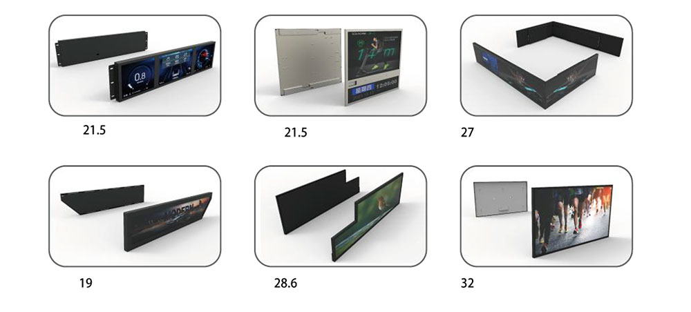
In practice, custom geometry requests fall into four families, each with different engineering trade-offs.
- Non-standard rectangular ratios. Panels such as 3:2, 16:10, 5:4 or 8:3 that sit between the common formats. These are the least disruptive to source, since they usually reuse existing cell designs and driver ICs.
- Portrait-native orientation. A 9:16 or 10:16 panel built as portrait rather than a landscape panel rotated in its frame. The distinction matters: rotating a landscape panel moves the flex tail and the backlight ingress to the wrong edge and often wastes 8–12 mm of height.
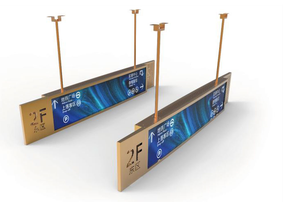
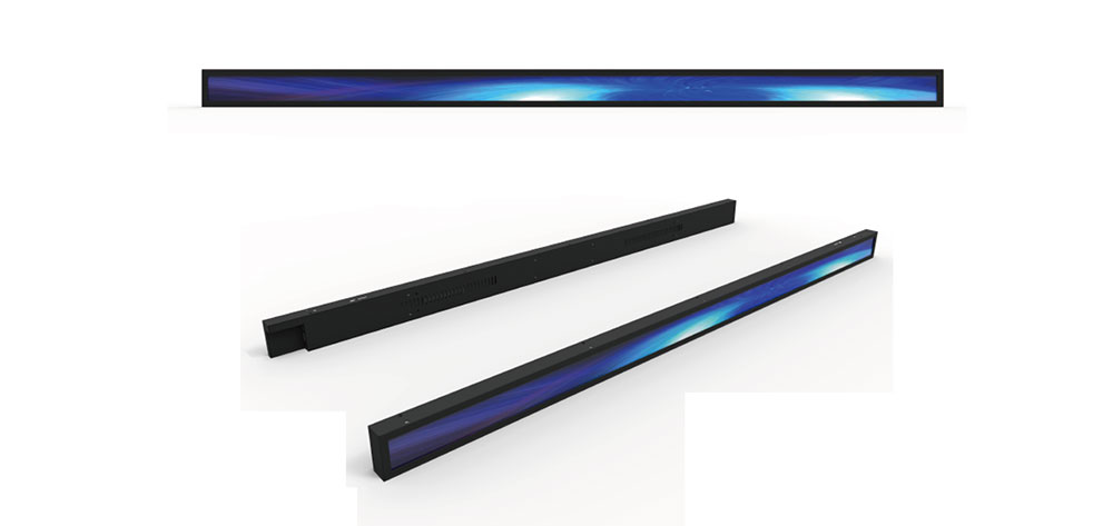
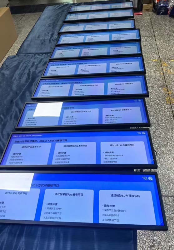
- Strip and bar formats. Very wide, very short active areas — 8:1, 12:1, even 20:1 — used for status bands, menu rails, ticker displays and appliance fascia. These are almost always cut from a shared substrate alongside other parts.
- Near-square and non-rectangular outlines. 1:1 formats for gauge clusters and instrumentation, plus rounded-corner, chamfered or notched active areas where the enclosure has a radius the display must follow.
The key engineering point is that a custom ratio is not a cosmetic request. It changes the pixel count, the gate and source line count, the driver IC channel allocation, the flex routing, the backlight cavity proportions and the mechanical stack. All of these must be resolved together, which is why the aspect ratio decision belongs at the concept stage and not at the BOM freeze.
The Geometry of Fit: Utilization Ratio Beats Diagonal Size
Buyers habitually compare displays by diagonal, which is the least useful number in a constrained enclosure. Two panels of identical diagonal can differ by more than 25% in usable area depending on ratio, and by considerably more once bezel is included.
A more honest metric is the aperture utilization ratio: the active area divided by the mechanical cut-out area the equipment can afford, expressed together with the bezel width on the two critical axes. A panel that is 3 mm narrower but has a 2 mm slimmer bezel on the long edge can deliver more usable pixels into the same housing than a nominally larger standard part.
| Envelope constraint | Standard 16:9 response | Custom-ratio response |
|---|---|---|
| Fixed 1U chassis height (44 mm) | Panel height forces a 4.3 in class part; large unused side area | Ultra-wide strip matches height; full width used for status and menus |
| Handheld body 68 mm wide | Panel width dictates housing; battery bay shrinks | 3:2 or 16:10 panel recovers 6–9 mm for cells or antenna clearance |
| Round gauge aperture | Rectangular panel behind a circular mask wastes corners | Near-square 1:1 with rounded corners fills the aperture |
| Portrait kiosk 9:16 opening | Landscape panel rotated; flex exits at the top, harness loops | Native portrait build; flex exits at the bottom, shorter run |
Design teams should also account for the active-area tolerance stack. Custom cells carry cut tolerances, polarizer placement tolerances and, where relevant, cover-glass print tolerances. Specifying an active area that matches the aperture to within 0.2 mm is achievable; specifying a zero-clearance edge is not, and usually produces a redesign at DVT.
Panel Economics: Cutting From the Mother Glass
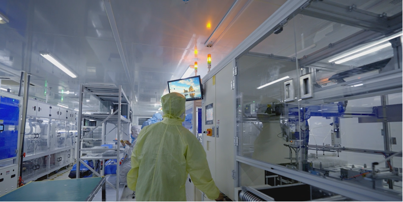
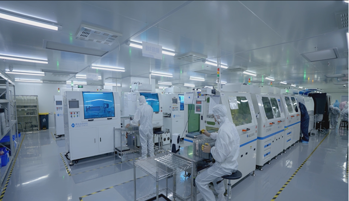
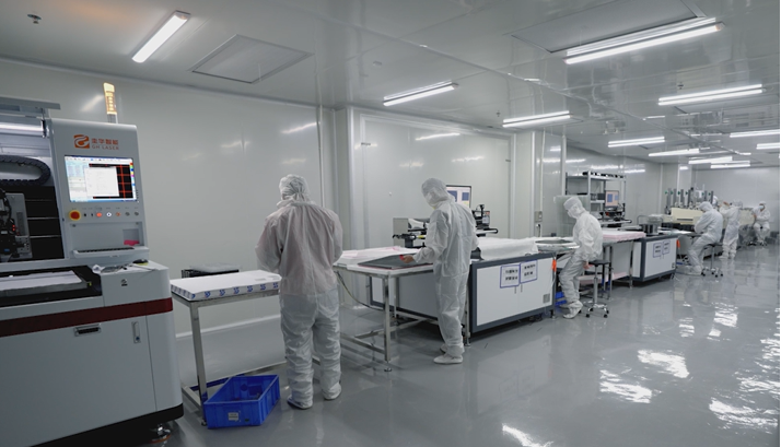
The reason custom ratios are affordable at all is that a panel is not manufactured individually — it is cut from a mother glass substrate, typically a Gen 4.5, Gen 5 or Gen 6 sheet. The cost of a custom part is dominated not by the cell itself but by how efficiently that cell tessellates the substrate.
A well-chosen custom ratio can actually be cheaper per unit than an off-the-shelf standard panel, because the supplier can pair it with a complementary part on the same sheet. An 8:1 strip leaves large rectangular offcuts; those offcuts are exactly the right shape for a 4:3 instrument panel, so a supplier running both parts gains yield on both. Conversely, a ratio that fits the substrate badly — one that leaves awkward slivers — will carry a permanent cost penalty and may never reach an attractive price point.
Three commercial levers determine whether a custom geometry is viable:
- Tooling and NRE. Mask set, cell layout, backlight mould, flex design and test fixture. This is a one-time cost, amortised across the programme, and it is the correct place to negotiate rather than the unit price.
- Cut efficiency. Ask the supplier directly what substrate generation they will run and what the sheet utilization is. A supplier who can answer that question quantitatively is a supplier who has actually modelled your part.
- Volume banding. Custom cells are usually quoted in bands, with a step at the tooling amortisation break-even. Ordering 20–30% above the band boundary, if forecasting allows it, frequently moves the unit price into the next tier.
Where volume genuinely cannot support a dedicated cell, a near-custom approach is often the right answer: an existing cell with a custom cover glass aperture, custom backlight and a bespoke mechanical frame. This delivers most of the mechanical fit benefit with a fraction of the NRE, and it can be executed in weeks rather than a full cell development cycle.
Resolution, Interface and the Timing Controller Problem
Aspect ratio and resolution are locked together. Choosing a 3:2 geometry means choosing a horizontal and vertical pixel count that the source driver can address and the timing controller can generate. Three constraints commonly surface.
First, driver IC channel count. Source drivers are available in fixed channel granularities, so a width that does not divide cleanly forces either unused channels — wasted cost — or a resolution change. Suppliers normally propose a resolution that lands on a clean channel boundary; engineers should expect that conversation and should arrive with an acceptable resolution band rather than a single number.
Second, TCON and host support. Many SoCs and GPUs publish a list of supported modes, and a non-standard resolution can fall outside the scaler's capability or trigger an unwanted aspect-preserving letterbox. Where the host cannot be changed, the display can often be given an on-board scaler or a fixed-mode TCON that presents a standard mode to the host and drives the panel natively. This is a common and inexpensive fix, but it must be designed in, not retrofitted.
Third, interface bandwidth and EMI. LVDS, MIPI DSI and eDP all impose practical limits that scale with pixel clock. A wide, short strip format has a high horizontal but low vertical count, which is generally favourable; a tall portrait format does the opposite. Interface choice also has EMC consequences, discussed below.
Optical Design at Non-Standard Shapes
High-brightness operation — typically 800 to 1,500 cd/m² for outdoor and sunlight-readable equipment, and higher for direct-sun applications — is where custom geometry becomes genuinely difficult. The backlight cavity is no longer a uniform rectangle. A 12:1 strip has very different light mixing behaviour from a 4:3 panel, because the distance from the LED array to the light guide edges is short relative to the length.
Practical mitigations include:
- Edge-lit with a custom light guide. LED pitch and light guide extraction pattern are recalculated for the new ratio. Uniformity is specified as a nine-point minimum, with 80% or better typical for instrumentation and 75% acceptable for status strips.
- Direct-lit arrays for short, wide formats. Where the height is too shallow for edge mixing, a low-count direct array behind a diffuser gives better uniformity at the cost of thickness and thermal load.
- Optical bonding. Bonding the cover glass or touch sensor directly to the polarizer removes an internal air gap, recovering 8–15% of luminance, improving contrast under ambient light and eliminating internal fogging in humid or wide-temperature service. For sunlight-readable custom panels this is usually the single highest-value optical decision.
- Circular polarizer and anti-reflective stacks. Particularly relevant where the operator wears polarised safety glasses or the equipment is used in the field at arbitrary viewing angles.
Brightness claims should always be qualified by the measurement condition: centre point or average, at what drive current, at 25 °C, after how many hours. A panel specified at 1,200 cd/m² centre and 950 cd/m² average is a different product from one specified at 1,200 cd/m² average, and the datasheet language should be checked before the mechanical design is fixed.
Mechanical and Interconnect Architecture
In space-constrained equipment, the flex tail is often the component that decides whether the design fits. A custom aspect ratio gives the opportunity to place the tail exactly where the board can accept it — bottom edge, side edge, or a double-bend tail that routes around a chassis rib.
Points worth specifying explicitly in the drawing package:
- Tail exit position and length, with a bend radius minimum and a defined stiffener zone for the connector.
- Connector type and orientation — ZIF, board-to-board or hot-bar soldered — matched to the assembly process and the number of mating cycles expected in service.
- Mounting datum. Custom panels should be dimensioned from the active area, not from the outline, so that the optical aperture is the controlled feature.
- Frame and gasket interface. Compression limits, foam hardness and the tolerance stack between the panel, the frame and the front bezel. Over-compression is the most common cause of mura and edge shadow in custom assemblies.
- Thickness budget. Panel, backlight, bonding layer, touch sensor and cover glass each contribute; a custom build allows the stack to be optimised per layer rather than accepted as a block.
EMC and Power Quality in the Finished Equipment
A custom display is electrically ordinary but geometrically unusual, and that has compliance implications in three areas.
Radiated emissions. A wide, short panel concentrates a large number of source lines and a long flex in a small volume. Shielding the flex with a grounded copper laminate, keeping the tail short and defining a low-impedance ground return to the chassis are the standard mitigations. Spread-spectrum clocking on the pixel clock should be evaluated early, since some TCONs provide it and some do not.
Conducted emissions and harmonic current. Where the end equipment is mains-powered, the display subsystem sits inside the harmonic envelope of EN 61000-3-2, with the AC/DC converter's input current shaping being the dominant contributor rather than the panel itself.
Flicker and voltage fluctuation. EN 61000-3-3:2013 limits voltage changes, voltage fluctuations and flicker injected into the public low-voltage supply by equipment drawing up to 16 A per phase. It is worth reading alongside the display's dimming design rather than treating as a power-supply formality. A high-brightness backlight dimmed by low-frequency PWM presents a periodically varying load; when the driver shares a supply rail with other high-current subsystems, or when the equipment draws significant power from a weak supply, the resulting fluctuation can become a measurable compliance and a visible-perception issue. Design responses include raising the PWM frequency above the perceptible band, reducing modulation depth by using analogue or hybrid dimming at low brightness levels, adding bulk capacitance and local decoupling at the backlight driver, and ensuring the dimming return does not share an impedance path with sensitive analogue circuitry. Where EN 61000-3-3 applies to the equipment, dimming behaviour should be characterised at the extremes — 1% and 100% brightness — not only at the nominal setting used for the emissions pre-scan.
ESD and transient immunity. Custom front assemblies should specify the air and contact discharge levels the cover glass and frame must survive, and confirm that the discharge path does not pass through the flex or the panel's grounding film.
Thermal Behaviour Inside a Sealed Enclosure
High brightness means heat, and constrained equipment usually means poor convection. Every additional 100 cd/m² of output carries a corresponding increase in backlight dissipation, and a sealed IP65 housing with no fan has only the front surface to work with.
The design levers are the familiar ones, applied earlier than usual: specify LED binning that meets the brightness target at a lower drive current rather than at maximum; use aluminium-backed or graphite heat-spreading layers behind the light guide; thermally couple the panel's rear surface to the chassis through a gap pad where a metal structure exists; and specify a brightness derating curve in the datasheet so the system design is not built on a 25 °C figure that cannot be sustained at 60 °C ambient. A custom geometry can also help here, because the light guide shape and LED placement can be chosen to distribute heat rather than concentrate it at one edge.
Reliability Qualification
Custom parts carry no less qualification burden than catalogue parts, and in constrained equipment the mechanical stresses are often higher. A realistic qualification programme for a custom-ratio industrial panel covers:
- Operating and storage temperature, commonly −30 °C to +80 °C operating for industrial grades, with a cold-start brightness check.
- Thermal shock and humidity soak, including a check for internal condensation where the panel is not optically bonded.
- Random vibration and mechanical shock to the levels of the end application — rail, vehicle or portable handheld.
- Drop testing at the assembly level, not the panel level, since the frame and gasket dominate the outcome.
- Backlight lifetime to a defined luminance fraction, typically 70% of initial, at a stated ambient and drive condition.
- Image sticking and mura inspection after extended static display, which is a real risk in equipment that displays the same menu for hours.
Programme Timeline and Commercial Structure
A fully custom cell is a development programme, not a purchase order. A realistic sequence runs: specification and feasibility, including a substrate cut study; optical and mechanical design; tooling; first samples; DVT and compliance; then production release. Elapsed time depends heavily on whether too KEYWORDS: Custom Aspect Ratio LCD Displays for Space-Constrained Equipment