Why Space Constraints Are Now a Primary Design Driver
Machine builders rarely start a project with extra room to spare. Enclosures shrink, bezels tighten, and every cubic centimeter behind the front panel is contested by power supplies, I/O boards, cooling paths, and cabling. In this environment, the display is no longer a simple off-the-shelf component dropped into a cutout. It becomes a mechanical, thermal, and optical subsystem that must conform to the geometry of the machine rather than forcing the machine to conform to it. Custom industrial LCD displays exist to resolve exactly this tension: delivering readable, durable, long-lifecycle visual output inside volumes that standard panels simply cannot occupy.
At HITULCD, the recurring request from equipment designers is not "a brighter screen" in isolation. It is "a brighter screen that fits here, survives this, and is still available in seven years." Space limitation ties all three of those demands together, because every gram and millimeter removed to save space affects thermal headroom, mechanical rigidity, and the choice of components that remain sourceable over a long production run.
What "Space-Limited" Really Means in Mechanical Terms
Space limitation is not a single dimension. It usually appears as a combination of constraints that must be solved simultaneously:
- Z-height (depth): The distance from the front glass to the rearmost component. Standard modules with tall backlight assemblies, thick PCBs, and bulky connectors often exceed the depth available behind a thin machine fascia.
- Active-area-to-outline ratio: How much of the module footprint is usable image versus dead border. In tight panels, a wide bezel wastes the only space you have.
- Connector orientation and exit direction: A connector that exits straight back may be impossible when another assembly sits directly behind the display. Side-exit or top-exit routing is frequently the deciding factor in whether a display fits at all.
- Mounting approach: Flange, bracket, bonded, or VESA-style fixing points each consume space differently and transfer mechanical load in different ways.
- Cable and FPC bend radius: In shallow cavities the flex cable cannot be bent sharply without risking fatigue failure, so the display design has to account for where and how the signal leaves the module.
Treating these as one combined envelope, rather than five separate specifications, is the core of designing for space-limited machines.
Reducing Z-Height Without Losing Performance
The backlight is usually the thickest part of an LCD module, so depth reduction begins there. Edge-lit LED backlights with a thin light guide plate can collapse the optical stack considerably compared to older direct-lit arrangements, while carefully selected diffuser and prism films recover uniformity. For high-brightness builds, the challenge is that more light output typically means more LEDs and more heat, which pushes back against the desire for a thin, sealed, compact assembly. The engineering answer is to balance LED binning, drive current, and heat spreading so the target luminance is reached without an oversized heatsink.
Depth can be reclaimed elsewhere too. Relocating the LED driver board, choosing low-profile connectors, thinning the metal bezel frame, and integrating the touch sensor directly onto the cover lens through optical bonding all remove millimeters that add up. Optical bonding deserves particular attention in constrained designs: by eliminating the air gap between the cover glass and the LCD, it not only improves contrast and sunlight readability but also stiffens the stack, allowing a thinner overall sandwich that still resists flex and impact.
Shaping the Outline: Cut Corners, Notches, and Non-Rectangular Formats
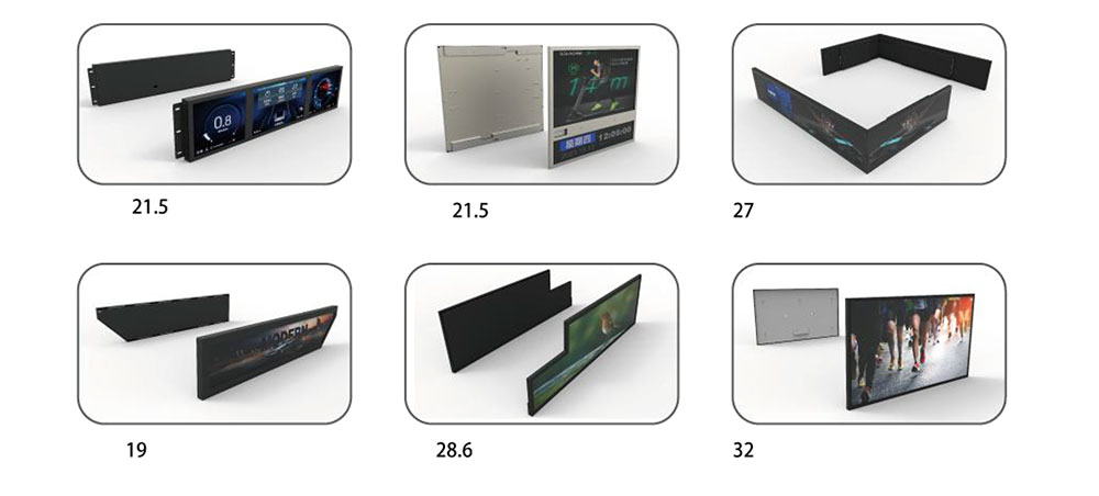
When a rectangular panel will not fit, the outline itself becomes customizable. Depending on the display technology and the position of the driver circuitry, it is often possible to modify the module outline with chamfered corners, mounting-screw clearances, and bezel cutouts that let the display nest around neighboring components. True free-form and notched active areas are more involved because they interact with the routing of row and column drivers, so these are scoped early with the engineering team rather than assumed. The guiding principle is that the display should follow the available cavity, filling awkward spaces instead of demanding a clean box.
Brightness and Thermal Management in a Small Volume
High-brightness displays and small enclosures are natural adversaries. Pushing a panel to 1000, 1500, or higher nits generates heat that, in an open setting, would dissipate freely but in a sealed, shallow machine housing has nowhere to go. Excess heat shortens LED life, can cause liquid-crystal "clearing" or blackening at elevated temperatures, and accelerates the aging of polarizers and adhesives.
For space-limited designs HITULCD approaches thermal control as a system problem. Strategies include spreading heat across a thin graphite or aluminum layer bonded to the rear of the module, selecting LEDs with higher luminous efficacy so fewer are needed for the same output, and using an ambient light sensor to drive automatic dimming so the panel only runs at full power when sunlight actually demands it. Automatic brightness control is especially valuable in compact builds because it dramatically lowers the average thermal load and extends service life, all without adding physical volume.
Mechanical Integrity and Environmental Sealing
A thinner, smaller display must not become a weaker one. Machines in factories, vehicles, outdoor kiosks, and medical equipment subject the front panel to vibration, shock, dust, moisture, and cleaning chemicals. Custom display assemblies address this with a cover lens sized and strengthened for the application, gasket and bonding schemes that support front-side ingress protection, and mounting geometry that carries load into the machine frame rather than into the glass. Where panel flatness and rigidity matter, optical bonding and a well-designed bezel work together so the compact stack still behaves like a solid structural member.
Touch Integration in Tight Bezels
Projected capacitive touch is the common choice for industrial interfaces, but it adds its own stack-up and border requirements for the sensor routing. In a narrow-bezel, space-limited design the touch sensor, cover lens, and LCD are co-designed so the touch border hides neatly behind the ink-printed frame of the cover glass, preserving the maximum active area. Controller tuning then ensures reliable operation with gloves, moisture on the surface, or thick protective lenses, which is where many generic touch solutions fail in real industrial conditions.
Interface, Connector, and Cable Strategy
In a cramped cavity, the way signals enter and leave the display is as important as the panel itself. Choosing the interface, LVDS, MIPI, eDP, or a parallel RGB bus for smaller panels, affects connector size and cable routing. Specifying connector position and exit direction up front prevents the common late-stage problem of a display that fits the cutout but cannot be wired because the connector collides with an adjacent board. Where appropriate, an integrated interface or driver board tailored to the customer's host system removes an external adapter and saves both depth and cabling.
Designing for Longevity and Supply Continuity
Industrial machines are built to run for a decade or more, so a space-optimized display is only successful if it remains available and consistent across that lifetime. Custom programs are built around long-lifecycle LCD panels, controlled bills of materials, and documented revision management so that a machine qualified today can be reproduced years from now without a surprise redesign. This is a core reason designers choose a dedicated industrial display partner rather than adapting consumer modules that may disappear from the market within a single product cycle.
From Requirement to Qualified Part: The Custom Workflow
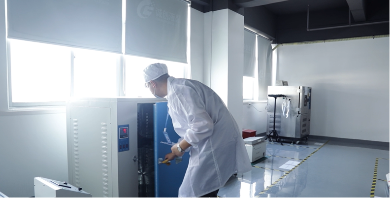
A practical custom project for a space-limited machine typically follows a clear path. It begins with capturing the full envelope: depth, outline, active area, brightness target, operating temperature range, interface, touch needs, and ingress requirements. Engineering then proposes a stack-up and outline that fit the cavity, with mechanical drawings and a thermal assessment. Samples are produced and validated against the machine, and once the customer confirms fit and function, the design is frozen with full documentation for repeatable mass production. Throughout, testing and validation are carried out under the agreed qualification plan, and no testing institution has been changed.
Conclusion
Space-limited machine design does not mean compromising on display quality. It means engineering the display as an integrated mechanical, thermal, and optical subsystem that is shaped to the machine. By controlling Z-height, customizing the outline, managing brightness-driven heat in small volumes, integrating touch within narrow bezels, and securing long-term supply, custom industrial LCD displays let designers reclaim precious internal space without sacrificing readability, durability, or longevity. For engineers facing a cavity that no standard panel will fit, a purpose-built HITULCD display turns a constraint into a solved design detail.
KEYWORDS: custom industrial LCD displays, space-limited machine design, high-brightness LCD, optical bonding, long-lifecycle displays