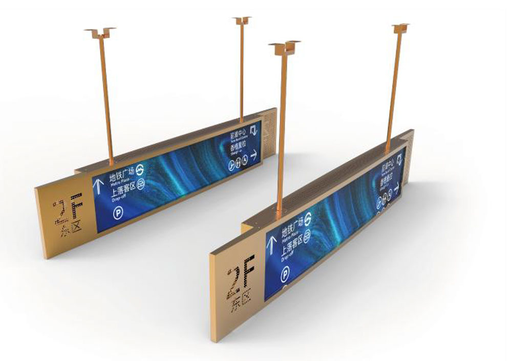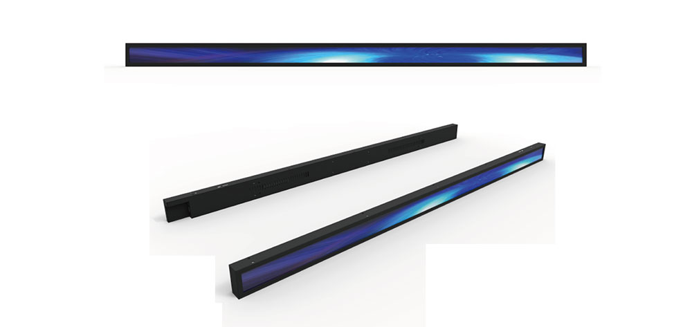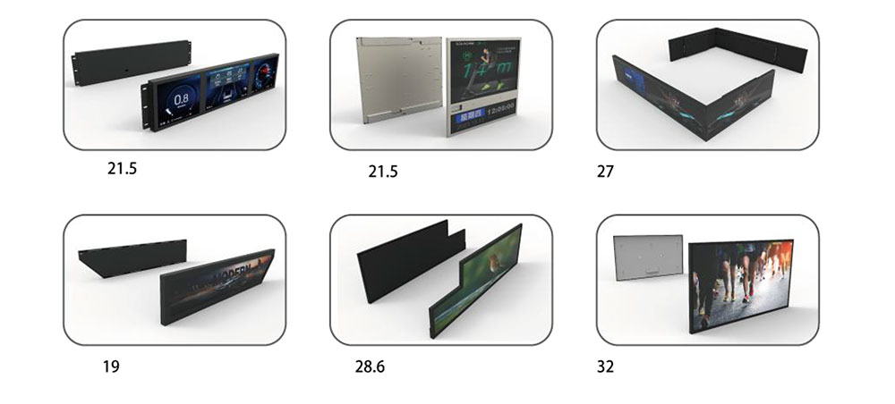
Bar-type LCD modules — the long, narrow panels often called stretched or strip displays — have moved from novelty to standard component in the British equipment sector. They appear in the door-height status panel of a train carriage, in the fascia of a laboratory analyser, in the shelf rail of a retail cabinet, in the annunciator strip of a control desk. Their appeal is simple: they occupy an aspect ratio that fits where a 16:9 panel cannot, and they let a machine present a line of information along an edge instead of demanding a square window on the front face.
For UK-based OEMs, integrating these displays is less about picking a pretty screen and more about engineering a component that will still be buildable, compliant and serviceable in ten years. This article sets out the practical engineering and procurement considerations behind that decision.
What Defines a Bar LCD Module
A bar module is generally any TFT panel with an aspect ratio of roughly 3:1 or wider. Common formats include 8.8-inch at 480×1920, 16.9-inch at 440×1920, 28-inch at 540×1920 and 37-inch at 420×1920, along with more specialised ratios such as 16:4.5 and 7:1 used in signage and transport applications. The active area is long and thin, but the electrical interface is ordinary: LVDS, MIPI DSI, eDP or parallel RGB, depending on resolution and refresh requirements.
Three construction grades dominate:
- Standard indoor modules with 300–500 cd/m² luminance, suitable for enclosed equipment cabinets and dimmed control rooms.
- High-brightness modules at 800–1500 cd/m², required for daylight-readable transport signage, outdoor kiosks and glazed factory environments.
- Ruggedised wide-temperature modules specified from −30 °C to +85 °C, used in rail, marine, agricultural and off-highway machinery.
Aspect Ratio as a Mechanical Constraint
The first design decision in British equipment is usually dimensional, not electrical. A 16.9-inch bar panel can replace a row of LEDs or a segmented display without changing the enclosure extrusion, which keeps tooling costs down and avoids a full mechanical redesign. Conversely, mounting and bezel design must account for the panel's low stiffness: a 500 mm long glass stack will flex under shock, so an aluminium or steel carrier frame with controlled clamping pressure is normally specified rather than simple corner mounts.
Where the module sits behind a sealed window, optical bonding of the cover glass to the panel is worth the cost. It removes the internal air gap, which eliminates condensation in cold-start conditions, cuts internal reflections and improves contrast under oblique viewing. For equipment installed in unheated buildings — agricultural stores, utility substations, unheated rail depots — that single change often decides whether the display is legible at 07:00 in February.
Brightness, Dimming and Thermal Load
High brightness is not free. Raising a backlight from 400 cd/m² to 1200 cd/m² roughly triples the LED drive power, and in a sealed bar format the heat has nowhere convenient to go. Two engineering responses dominate:
- Automatic brightness control using an ambient light sensor, so the panel runs at 200–300 cd/m² in a dim control room and only reaches full output in daylight. This cuts average power and extends LED life.
- High-frequency PWM or constant-current analogue dimming. Dimming below roughly 200 Hz is visible to some operators as strobing, and in machine-vision-adjacent installations it can interact with camera frame rates. Above 20 kHz, audible backlight noise becomes the risk instead, so around 1–5 kHz is a common compromise.
Thermal design should be checked at the worst case, not the nominal case: full brightness, high ambient, equipment cabinet closed, and the module mounted horizontally with heat rising into the panel's own frame. Where natural convection is insufficient, a bonded metal backplate or a small cabinet fan is usually cheaper than derating the backlight and compromising daylight readability.
Interface and Signal Integrity
Bar modules are electrically conventional but mechanically awkward for cabling. A 1920-pixel-wide panel driven over LVDS needs careful routing: keep the differential pairs matched, avoid sharp 90° bends, and do not run display cables alongside VFD or servo drive wiring without separation and shielding. For longer internal runs — common in a large machine where the controller sits in a separate bay — embedded DisplayPort or a serialised link with a bridge chip is often more robust than pushing LVDS beyond its comfortable length.
From an EMC standpoint, British equipment is typically assessed against the BS EN 55032 emission and BS EN 55035 immunity standards, or the relevant machinery and rail equivalents. Displays rarely fail emissions on their own, but their ribbon cables are efficient antennas. Ferrite sleeves at the connector, a grounded shield layer and a clean backlight driver return path solve most issues before they reach the test house.
Touch, Cover Glass and Front-Face Options
Many bar installations are read-only, but where operator input is needed, projected capacitive touch is the default. In industrial settings the touch sensor is usually laminated behind chemically strengthened glass with an anti-glare or anti-fingerprint treatment. Where the display forms part of a washdown-rated panel, the front face must meet the relevant ingress protection rating, and the bond between glass and housing becomes a sealing element rather than a cosmetic one.
Compliance and Documentation for the UK Market
Compliance is where component selection quietly determines a project's schedule. A display module placed on the UK market must satisfy the Restriction of Hazardous Substances regulations, and purchasers increasingly want documentary evidence rather than a verbal assurance. HITULCD publishes its declaration of conformity alongside the product range, and the RoHS certificate for LCD screens is available to download for inclusion in a technical file.
Beyond RoHS, British manufacturers should expect to gather:
- A declaration of conformity covering electrical safety and EMC of the assembled product.
- UKCA marking documentation for the finished equipment, referencing the display's own CE/UKCA status where relevant.
- Reach SVHC statements, particularly for adhesives, gaskets and PCB finishes.
- Conflict-minerals and, increasingly, carbon-footprint data requested by rail and public-sector customers.
It is also worth confirming lithium-free packaging and recyclable materials where the customer operates under a waste electrical and electronic equipment obligation.
Supply Longevity and Change Control
The hardest part of specifying a bar display is not the datasheet, it is the five-to-ten-year availability question. Railway rolling stock, medical analysers and industrial instruments are supported for far longer than a consumer panel generation. Mitigations include:
- Choosing modules from a manufacturer that commits to a fixed product-life statement and a notification window before end-of-life.
- Qualifying a second source or a pin-compatible drop-in early, even if volumes do not yet justify dual sourcing.
- Buying a lifetime buffer stock for the last build, accounting for field-service replacements at roughly 2–4 % of installed units per year.
- Keeping the mechanical interface stable across generations so a future module can be fitted without retooling the enclosure.
Change notifications deserve particular attention. A backlight LED binning change can shift colour temperature by several hundred Kelvin; a driver IC revision can alter power-up timing. Both are minor on paper and disruptive in the field, so a documented change-control agreement belongs in the purchase contract.
Specification Checklist for UK OEMs
| Parameter | Typical industrial requirement | Notes |
|---|---|---|
| Diagonal / aspect | 8.8"–37", 3:1 or wider | Driven by enclosure geometry |
| Luminance | 800–1200 cd/m² | Higher for daylight or glazed sites |
| Contrast | 1000:1 minimum | Bonded glass raises effective contrast |
| Operating temperature | −30 °C to +80 °C | Check storage and cold-start behaviour |
| Interface | LVDS or eDP | Length and shielding dictate the choice |
| Backlight life | 50,000 h to 50 % | Derate for full-brightness duty |
| Dimming | PWM or analogue, 100:1 | Above 200 Hz to avoid flicker |
| Compliance | RoHS, REACH, UKCA chain | Documentation in the technical file |
Where Bar Displays Earn Their Place
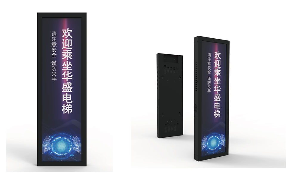
The strongest case for a bar module is where information must be presented along an edge that already exists. Transport interior and platform signage, machine status rails, kiosk headers, vending and ticketing fascias, medical bedside strips, marine bridge repeaters, and process-control annunciators all fall into this category. In each case the alternative is either a segmented display with no graphical capability or a conventionally shaped panel that forces a mechanical redesign.
Choosing correctly comes down to three questions: what is the worst-case ambient light and temperature, how long must the equipment stay in service, and what documentation will the customer's technical file require. Answer those before the datasheet review, and the bar display becomes one of the least troublesome components in the build rather than the one that delays the launch.
KEYWORDS: industrial bar LCD display module, stretched LCD panel, high brightness bar display, LVDS bar LCD, UKCA industrial display