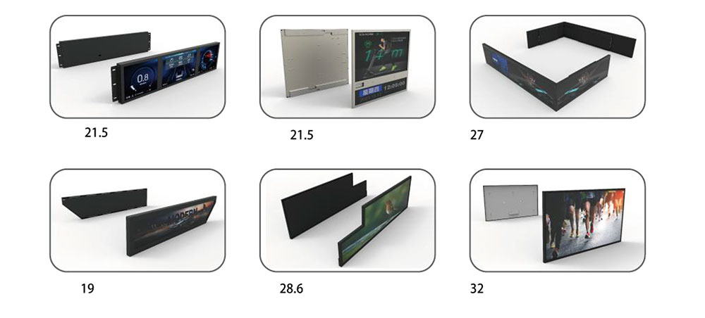
Multi-Channel Independent Backlight Control for Edge-Lit Stretched Bar LCD Displays
An engineering-focused approach to an edge-lit LCD architecture with eight backlight control circuits, four external controllers, and PWM or analog dimming options.

1. Backlight Control Designed Around the Application
In many conventional LCD modules, backlight brightness is adjusted as one common output. This is suitable for a wide range of display applications, but it may not provide enough flexibility for equipment manufacturers who need to adjust different LED backlight circuits independently.
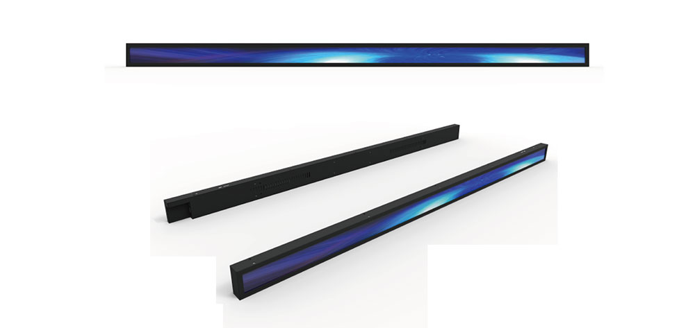
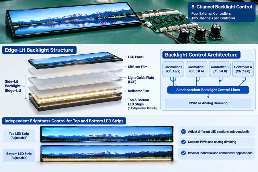
HITULCD's customized stretched bar LCD solution uses an edge-lit backlight architecture, with LED strips positioned along the upper and lower edges of the display assembly. The LEDs inject light into the light guide plate (LGP), which distributes the light across the viewing area.
The backlight electronics are arranged as eight separately adjustable circuits. Four external backlight controllers are used, with each controller assigned to two circuits. The dimming method can be configured for PWM or analog control according to the selected driver implementation.
2. Edge-Lit Backlight Structure: LEDs Along the Top and Bottom Edges
Unlike a direct-lit design, which places LED sources behind the display area, an edge-lit backlight introduces light from the sides of a light guide plate. In this configuration, LED strips are located along the upper and lower edges of the assembly.
The light guide plate uses its optical geometry and extraction features to distribute incoming light across the panel area. Reflective and diffusion films help manage light direction and reduce visible non-uniformity.
LED strips
Located along the upper and lower edges. The LED circuits are divided into separately controlled electrical sections.
Light Guide Plate (LGP)
Receives light from the edge-mounted LEDs and distributes it across the display area.
Reflector and diffuser films
Help redirect and spread light to support the required optical uniformity.
LCD panel
Modulates transmitted light to form the image. Backlight adjustment does not require changing the incoming image signal.
The mechanical position of the LED strips, the LGP thickness, optical extraction pattern, reflector and diffuser selection all influence the final result. These parameters should be evaluated as one optical assembly rather than as isolated components.
3. Eight Backlight Circuits and Four External Controllers
The control arrangement is based on four external backlight controllers. Each controller is assigned to two backlight circuits, providing eight separately adjustable electrical circuits in total.
| External controller | Assigned circuits | Quantity |
|---|---|---|
| Controller 1 | Backlight circuit 1 and 2 | 2 circuits |
| Controller 2 | Backlight circuit 3 and 4 | 2 circuits |
| Controller 3 | Backlight circuit 5 and 6 | 2 circuits |
| Controller 4 | Backlight circuit 7 and 8 | 2 circuits |
This arrangement gives equipment designers a defined hardware interface for adjusting the brightness of the corresponding LED circuits. The exact channel assignment, connector pinout, signal reference and wiring should be documented in the project-specific electrical drawing.
The eight control lines should not be treated as generic power wires. Their electrical function and signal characteristics must be specified by the driver design, including whether the selected implementation uses PWM or analog dimming.
4. PWM and Analog Dimming Options
PWM dimming
Pulse Width Modulation controls the average LED output by changing the duty cycle of a switching signal. A higher duty cycle generally produces greater average light output, while a lower duty cycle reduces it.
PWM can provide a broad dimming range, but the frequency, duty-cycle resolution, minimum brightness and signal integrity need to be considered. Applications involving cameras or machine vision should be checked for flicker or rolling-shutter banding at the intended operating settings.
Analog dimming
Analog dimming regulates LED brightness by changing the current reference of the LED driver. It can provide continuous adjustment, subject to the driver's supported current range and stability.
At low current levels, LED color and output characteristics may change. The minimum stable current and brightness range should therefore be verified for the selected LED and driver combination.
| Consideration | PWM dimming | Analog dimming |
|---|---|---|
| Control principle | Changes switching duty cycle | Changes regulated LED current |
| Key design checks | Frequency, flicker, EMI and resolution | Current range, stability and color shift |
| Selection | Choose according to the LED driver, optical target and host-equipment requirements. | |
5. Electrical Control and Optical Performance Must Be Evaluated Separately
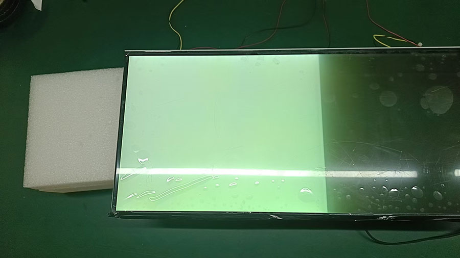
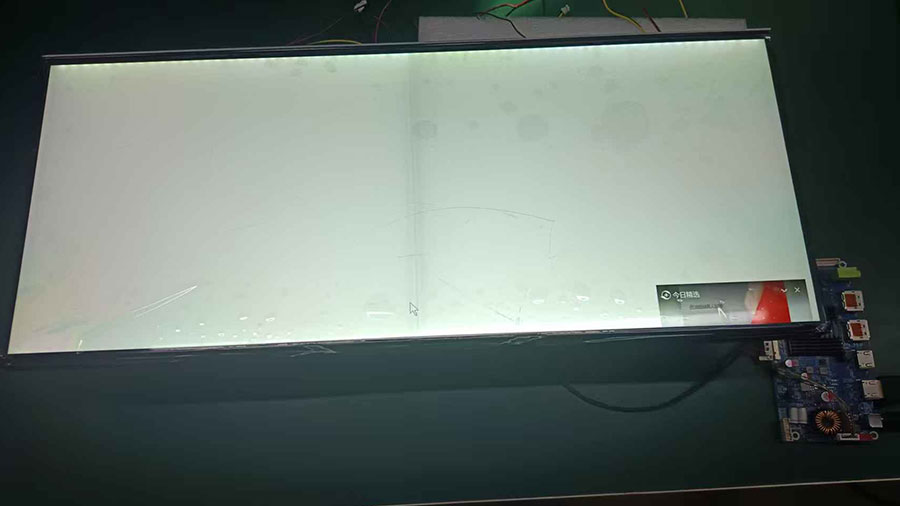
Independent electrical control does not automatically mean that each circuit illuminates a completely isolated area of the LCD. In an edge-lit system, light enters the LGP and spreads through the optical structure. A change in one LED circuit may therefore influence illumination beyond the immediate physical position of that circuit.
For this reason, engineering validation should consider both the electrical response of each channel and the measured luminance distribution across the finished display.
Measure luminance at defined points across the display at representative channel settings.
Check the transition between adjacent LED sections for visible brightness gradients.
Evaluate the full-brightness condition with all required circuits operating simultaneously.
Check minimum brightness, channel repeatability and dimming response.
Assess thermal behavior of the LED strips, driver components and enclosure.
For PWM configurations, verify flicker and camera compatibility where relevant.
6. Integration Considerations for OEM Equipment
For an OEM project, the display should be evaluated as part of the host equipment rather than as a standalone panel. The control interface, cable routing, power budget and thermal environment can all affect system performance.
Electrical interface: Confirm control voltage levels, signal reference, connector pinout and cable requirements.
Dimming configuration: Define whether PWM or analog dimming is used and specify the supported operating range.
Power budget: Verify the supply capacity for simultaneous operation of the required LED circuits.
Thermal design: Evaluate LED and driver temperatures in the actual enclosure and operating environment.
Optical validation: Check luminance uniformity and visible transitions under the intended settings.
Mechanical integration: Confirm mounting, edge clearance, cable exit and service access.
7. Potential Applications
Industrial HMI and control panels
Customized operator interfaces where different backlight circuits may require separate brightness settings.
Instrumentation and test equipment
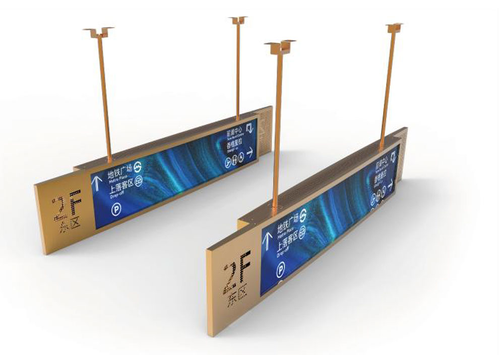
Wide-format display integration for specialized instruments and monitoring systems.
Transportation equipment
Custom display assemblies for vehicle or transportation-related equipment, subject to application-specific validation.
8. HITULCD Customization for OEM and ODM Projects
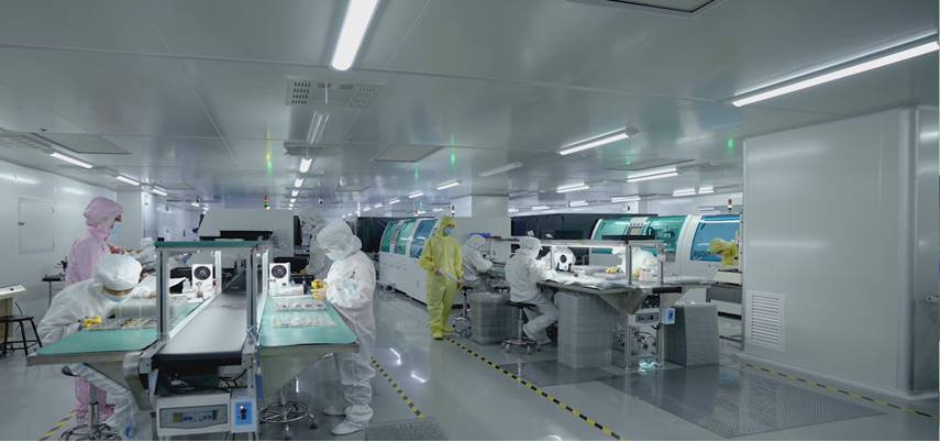
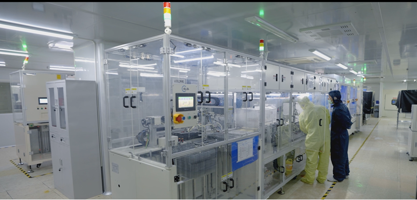
HITULCD works with equipment manufacturers and display integrators on customized LCD configurations. For projects requiring multi-channel edge-lit backlight control, the development discussion can cover the LCD panel, upper and lower LED strip arrangement, eight-circuit control architecture, dimming method, mechanical structure and host-system interface.
Project specifications should be finalized against the selected panel and driver design. Available screen dimensions, brightness, electrical limits, optical uniformity and environmental ratings should be confirmed for each configuration rather than assumed from the general architecture.
Discuss Your Custom Edge-Lit LCD Project
Looking for a stretched bar LCD with independently adjustable backlight circuits? Share your display dimensions, required number of control channels, preferred dimming method and equipment interface. HITULCD can review the requirements for a project-specific solution.
Contact HITULCD to discuss your OEM / ODM display requirements.
Technical note: This article describes the stated product architecture. Final electrical pin assignments, channel distribution, luminance performance, thermal limits and environmental specifications must be confirmed using the applicable product drawings and validation results.
KEYWORDS: