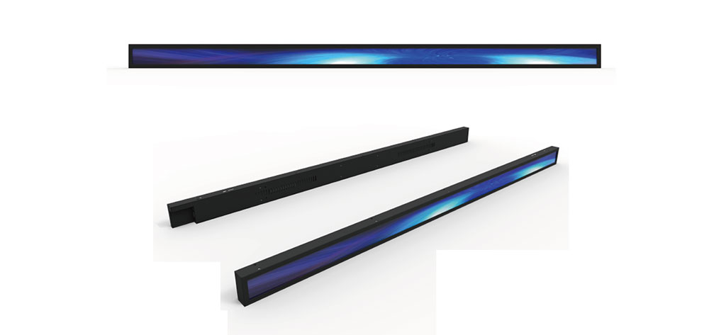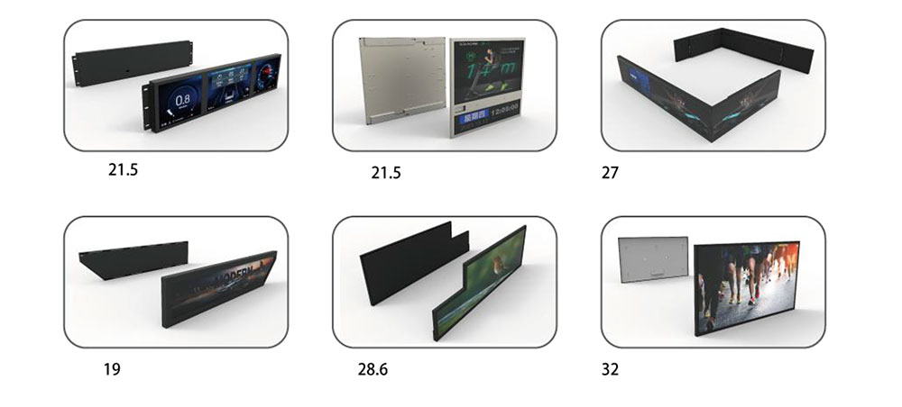
Edge-Lit Bar-Type LCD with Independent Zone Backlight Control
Independent Brightness Adjustment | 8 Dimming Channels | 4 Control Zones
Published: November 3, 2026 | By HITULCD Engineering Team
1. Why Long LCD Displays Need Independent Brightness Control
Ultra-wide bar-type LCD displays are widely used in industrial equipment, transportation systems, retail displays and vehicle applications.
However, their elongated screen format creates a particular challenge: ambient lighting conditions are often different across the display.
For example:
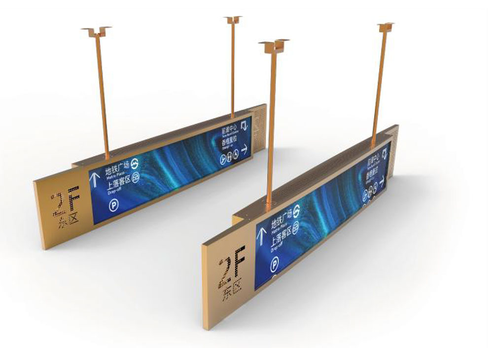
Transportation: One end of a passenger information display may face direct sunlight while the other remains in the shade.
Industrial equipment: Different sections of a machine control display may be exposed to different lighting conditions.
Retail environments: A promotional area may need higher brightness while other sections can operate at a lower level.
With a conventional backlight, the entire screen shares one brightness setting. Increasing brightness to improve visibility in one area can make other areas unnecessarily bright.
HITULCD's independent zone backlight control solution addresses this issue by allowing different sections of an ultra-wide LCD to operate at different brightness levels.
2. HITULCD Independent Zone Backlight Solution
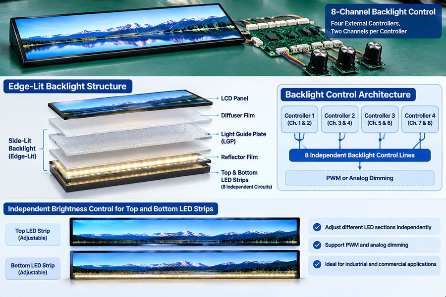
The solution uses an edge-lit LED backlight structure with 8 independent dimming channels and 4 independently adjustable brightness zones.
How the Backlight Structure Works
LED light bars are installed along the top and bottom edges of the LCD panel. There are no LED light bars along the left or right edges.
A light guide plate (LGP) distributes the light from these LED bars across the LCD's active display area.
The backlight configuration consists of:
4 LED dimming channels along the top edge.
4 LED dimming channels along the bottom edge.
4 independent backlight controllers.
Each controller operates one top-edge channel and one corresponding bottom-edge channel.
The corresponding top and bottom channels work together to illuminate one vertical section of the display.
Backlight Configuration:
| Component | Configuration |
|---|---|
| LED installation | Top and bottom edges only |
| LED dimming channels | 8 independent channels |
| Top-edge channels | 4 |
| Bottom-edge channels | 4 |
| Backlight controllers | 4 |
| Independently adjustable zones | 4 |
This architecture provides four independently adjustable brightness zones across the horizontal direction of the bar-type display.
3. Key Technical Features
3.1 Independent Brightness Adjustment Across Four Zones
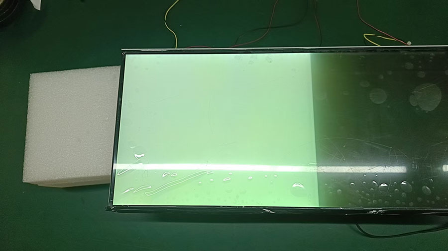
Each of the four zones can be adjusted independently or operated at a coordinated brightness level.
Typical configurations include:
Higher brightness on the left and lower brightness on the right.
Four different brightness levels corresponding to changing ambient light conditions.
Reduced brightness in non-critical areas to help lower overall backlight power consumption.
This is particularly useful for long displays installed in environments where lighting conditions vary across the screen.
3.2 Thin Edge-Lit Backlight Architecture
The edge-lit structure is suitable for ultra-wide LCD modules where installation thickness, mechanical space and thermal management are important design considerations.
| Design Factor | Edge-Lit Backlight | Direct-Lit Backlight |
|---|---|---|
| Module thickness | Thin structure | Requires LED-to-panel mixing distance |
| LED quantity | Relatively low | Relatively high |
| Power and cost | Generally lower | Generally higher |
| Thermal management | Heat concentrated along edges | Heat distributed across the rear |
| Maintenance | Relatively simple structure | More LED components |
| Dimming configuration | Segmented control along the long axis | Supports two-dimensional zoning |
The final architecture depends on display dimensions, optical requirements and the intended installation environment.
3.3 Multiple Backlight Control Options
HITULCD can configure the backlight control interface according to the customer's system requirements.
Option A: Manual Controller with Adjustment Knobs
Four dedicated controllers can be supplied, each with an adjustment knob for its corresponding brightness zone.
This allows technicians to adjust brightness directly during installation or maintenance without requiring host software.
Option B: External PWM Control
The backlight can interface with an external PWM output from the customer's main control system.
This allows brightness adjustment to be managed through the equipment's existing control architecture.
Option C: Analog Voltage Control
Analog dimming interfaces, such as 0–10 V, can be configured according to project requirements.
Option D: Ambient Light Sensor Integration
For applications requiring automatic brightness adjustment, the system can be integrated with ambient light sensors and a host controller.
Engineering note: The eight dimming lines are control signal channels, not direct connections for ordinary potentiometers. A dedicated backlight driver circuit, including constant-current LED driving and dimming control, is required to maintain stable LED current.
3.4 PWM and Analog Dimming Technologies
Different applications require different dimming characteristics.
| Dimming Method | Main Advantages | Design Considerations |
|---|---|---|
| PWM Dimming | Wide dimming range and stable LED color temperature | Frequency must be selected to minimize visible flicker and camera banding |
| Analog Dimming | Suitable for flicker-sensitive applications | Low-brightness accuracy and color temperature variation require evaluation |
For applications involving cameras, medical equipment or control rooms, dimming frequency and flicker performance should be evaluated during the design stage.
High-frequency PWM or analog dimming can be selected according to the application. Hybrid dimming is also available as a design option.
4. What This Technology Is — and What It Is Not
It is important to distinguish this solution from more complex local dimming technologies.
What it provides:
Edge-lit LED backlight architecture.
Four independently adjustable brightness zones.
Eight LED dimming signal channels.
Manual or external system-based brightness control.
Customizable PWM or analog dimming interfaces.
RGB backlight color adjustment.
Independent color control for each zone.
Content-adaptive local dimming.
How Do the Brightness Zones Transition?
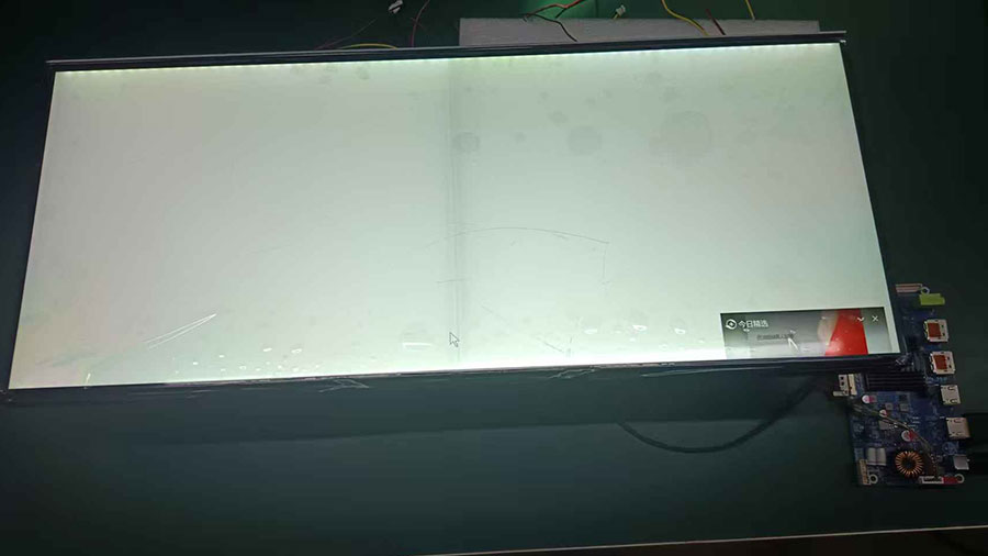
Because this is an edge-lit structure using a light guide plate, adjacent zones produce a gradual brightness transition rather than a completely sharp dividing line.
This helps create a more natural visual appearance.
For projects requiring more distinct brightness boundaries, optical isolation within the light guide plate can be evaluated as a custom engineering option.
5. Reference Technical Specifications
The following table provides typical reference configurations. Final specifications are confirmed according to the actual display design.
| Parameter | Reference Specification |
|---|---|
| Backlight Type | Edge-lit LED |
| LED Position | Top and bottom edges |
| Dimming Channels | 8 (4 top + 4 bottom) |
| Independent Zones | 4 |
| Backlight Controllers | 4 |
| Dimming Method | PWM / Analog |
| Dimming Ratio | 100:1 (1%–100%) with PWM |
| PWM Frequency | 1–20 kHz |
| PWM Input | 3.3 V / 5 V logic level |
| Analog Input | 0–10 V |
| Typical Brightness | 1,000 cd/m² |
| Brightness Options | 500–1,500 cd/m² |
| Common Resolutions | 1920 × 360 / 1920 × 540 / 1920 × 720 |
| Display Interface | LVDS; eDP / HDMI via driver board |
| Input Voltage | 12 V DC; optional 9–36 V DC |
| Standard Operating Temperature | 0°C to +50°C |
| Wide Temperature Option | −20°C to +70°C |
| Typical LED Lifetime | 50,000 hours (to 50% of initial brightness) |
Custom sizes, resolutions, brightness levels, interfaces and operating temperature ranges can be evaluated for individual projects.
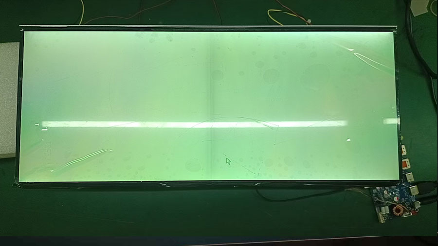
6. Typical Industrial and Commercial Applications
Independent zone brightness control is useful in applications where long LCD displays operate under uneven ambient lighting.
Industrial HMI and Control Panels
Different sections of an industrial control panel may face different lighting conditions. Independent brightness adjustment allows operators to configure each section according to the installation environment.
Railway and Public Transportation Displays
Passenger information displays installed on platforms, inside stations or near tunnel entrances may experience significant changes in ambient lighting.
Vehicle and Marine Equipment
Displays used in vehicles, ships and specialty equipment may require different brightness settings between operating conditions, particularly during nighttime operation.
Medical and Laboratory Equipment
Independent brightness adjustment can help adapt different display areas to the lighting requirements of laboratory and equipment environments.
Retail Shelf Displays and Digital Signage
Promotional content can be displayed at higher brightness while other sections operate at reduced brightness.
Semi-Outdoor Equipment and Self-Service Kiosks
The backlight architecture can be combined with higher-brightness LCD panels for applications exposed to strong ambient light.
7. Engineering Considerations Before Integration
For OEMs and equipment manufacturers, several engineering factors should be considered before finalizing the backlight configuration.
1. Thermal Management
LED heat is concentrated along the top and bottom edges. A suitable metal back plate, aluminum-core light bar and thermal path should be incorporated into the mechanical design.
2. Constant-Current LED Driving
Each LED string should be driven by a suitable constant-current circuit to minimize brightness variations caused by voltage drop and temperature changes.
3. Zone Brightness Calibration
The drive current of each zone should be calibrated to achieve the required brightness consistency. Unit-by-unit calibration can be specified before shipment.
4. Flicker Performance
PWM frequency should be selected according to the application. For flicker-sensitive installations, relevant industry guidance, including IEEE 1789, should be considered during design evaluation.
5. Electromagnetic Compatibility
PWM switching can generate electromagnetic interference. Wiring layout, grounding, shielding and filtering should be addressed early in the integration process.
6. Control Interface and User Experience
For manual adjustment, each controller should have a clearly identified zone label and adjustment scale to prevent operating errors.
8. Compliance Considerations for European and North American Projects
Depending on the final product and application, customers may need to evaluate the following standards and regulatory requirements.
| Area | Relevant Standards / Requirements |
|---|---|
| Product Safety | IEC / UL 62368-1 |
| Medical Equipment Safety | IEC 60601-1 |
| EMC | EN 55032 / EN 55035 |
| US EMC Requirements | FCC Part 15 |
| Environmental Compliance | RoHS / REACH |
| Railway Applications | EN 50155 |
| Marine Applications | IEC 60945 |
| Automotive Applications | ISO 7637 / E-mark, as applicable |
The applicable standards, certification scope and testing requirements depend on the final equipment configuration and target market.
Compliance documentation and testing arrangements can be discussed during project evaluation.
9. Frequently Asked Questions
Q1. Can the left and right sides of the display be adjusted independently?
Yes. The system provides four independently adjustable brightness zones distributed across the horizontal direction of the display.
Q2. Can different zones display different backlight colors?
No. This solution controls brightness only. It does not provide RGB color adjustment or independent color control. RGB or tunable-white backlighting can be evaluated as a separate custom solution.
Q3. Can I connect a potentiometer directly to the dimming channels?
No. The dimming signals must be connected through a dedicated backlight driver and dimming controller. HITULCD can provide matching controllers or interface with the customer's PWM or analog control system.
Q4. Will PWM dimming cause visible flicker?
Flicker performance depends on PWM frequency, dimming depth, driver design and the application. High-frequency PWM or analog dimming can be selected for applications with stricter flicker requirements.
Q5. Will there be visible boundaries between brightness zones?
The light guide plate produces gradual brightness transitions between adjacent zones rather than sharp boundaries. Optical isolation can be evaluated if more distinct transitions are required.
Q6. Can the solution be customized for different LCD sizes?
Yes. Display dimensions, resolution, brightness, number of zones, control interfaces, operating temperature and mechanical structure can be evaluated according to your project requirements.
10. Develop Your Custom Bar-Type LCD with HITULCD
HITULCD provides customized bar-type LCD modules and backlight integration solutions for industrial equipment manufacturers, transportation system integrators, retail display manufacturers and OEM/ODM customers.
Whether your project requires four-zone brightness adjustment, a customized ultra-wide resolution or integration with an existing equipment control system, our engineering team can evaluate the appropriate display configuration.
Tell us about your project:
Application and installation environment
Required LCD size and resolution
Target brightness
Number of independent brightness zones
Preferred control method (PWM / Analog / Manual)
Operating temperature requirements
Contact HITULCD to discuss your custom edge-lit bar-type LCD solution and request technical specifications or an engineering sample.
KEYWORDS: