Passenger information has quietly become one of the most visible measures of transit service quality in Canada. Riders judge a system by whether the sign above the window tells them, accurately and instantly, which bus they are boarding, where it stops next, and whether the trip is accessible. For decades, that job was done by amber LED dot-matrix panels — rugged, cheap, and limited to two lines of blocky characters. The stretched bar LCD is the replacement, and it brings with it a set of engineering problems that are distinctly Canadian: a −40 °C Prairie cold start, a +65 °C solar soak behind a windshield, chloride brine on the exterior body, and a legislated obligation to present information in both official languages, legibly, to every rider.
This paper examines the bar-format LCD as a subsystem rather than a component: how its geometry interacts with bus interior packaging, how Canadian thermal and electrical environments shape panel selection and enclosure design, how bilingual and accessible content requirements constrain pixel layout, and what a procurement specification should actually say when a fleet buys its next generation of onboard displays.
1. Defining the Bar Format
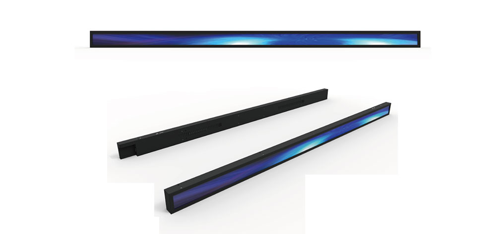
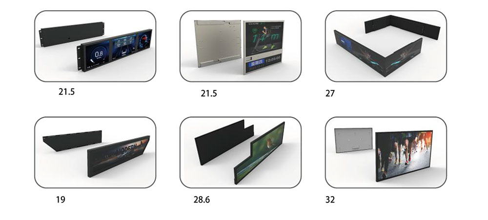
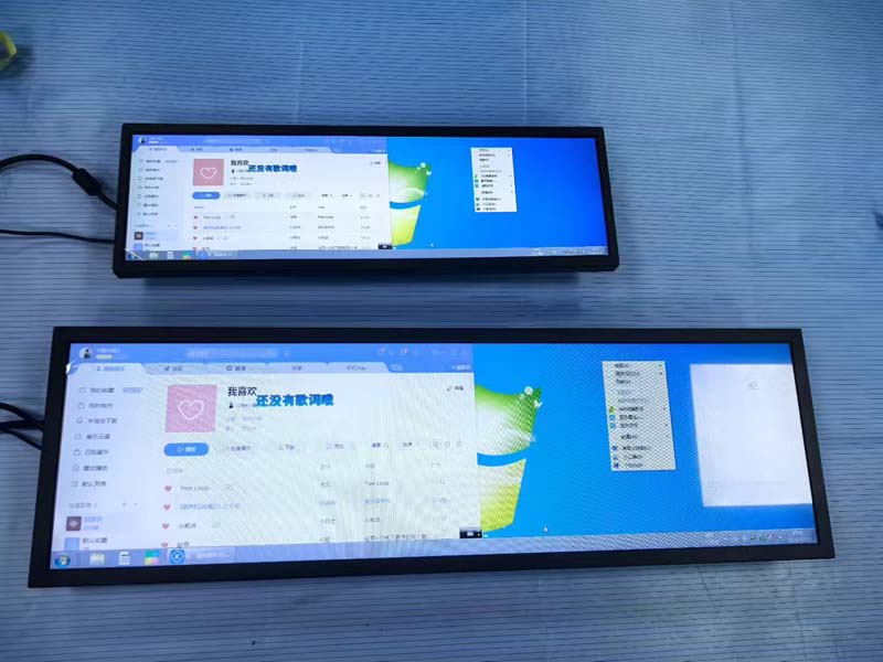
A stretched bar LCD is a standard active-matrix TFT panel cut to a wide, shallow aspect ratio — typically between 3.5:1 and 6:1 — rather than the 16:9 of consumer displays. Common configurations in transit applications include 1920 × 480 (4:1), 1920 × 540 (3.56:1), 2880 × 540, and 3840 × 720 (5.33:1), with diagonals from roughly 19 to 37 inches. Because the panel is cut from the same generation glass as conventional displays, the pixel density is modest: a 28.9-inch 1920 × 480 panel delivers an active area of approximately 712 × 178 mm and a pixel pitch near 0.37 mm.
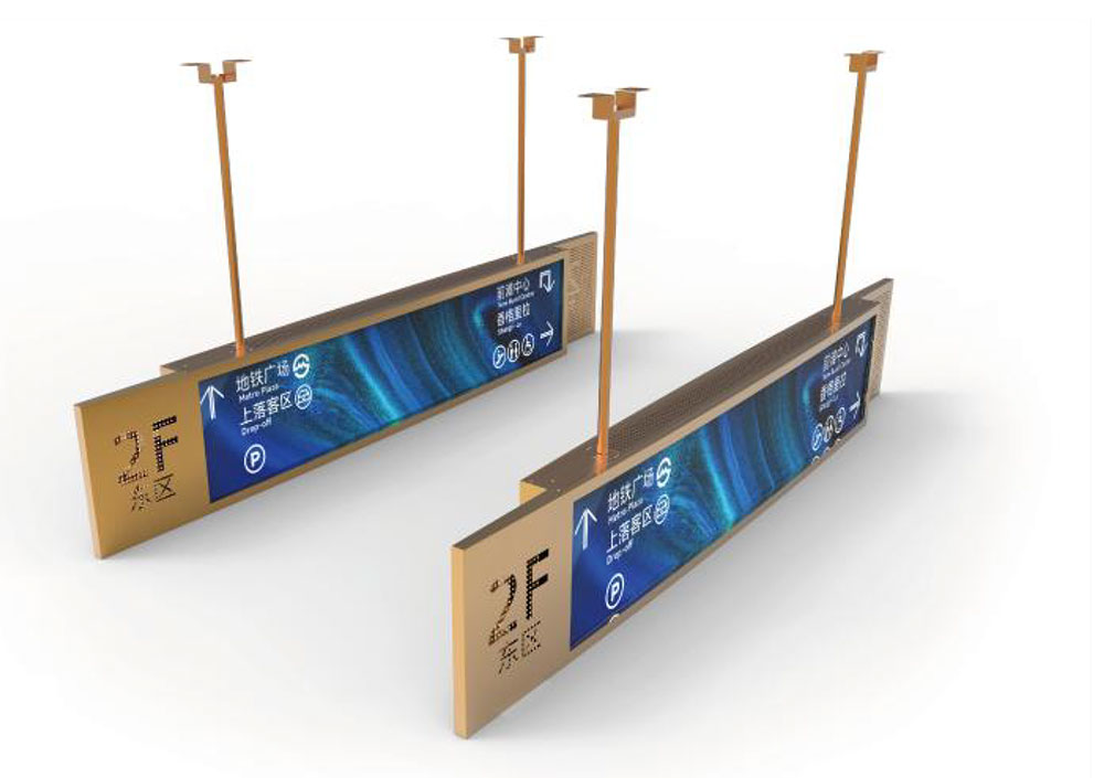
That geometry is the whole point. The header zone above a bus window is usually only 150–200 mm tall, and the strip behind the front bulkhead is narrower still. A 16:9 display either overflows that band or wastes most of its area on a poster-shaped image. A bar panel fills the architectural slot exactly, edge to edge, with a bezel of 10–15 mm and no dead space.
| Parameter | Typical interior bar display | Typical exterior / behind-glass sign |
|---|---|---|
| Diagonal / aspect | 28.9 in, 4:1 (1920 × 480) | 28–37 in, 3.56:1 to 5.33:1 |
| Luminance | 700–1,200 cd/m² | 2,000–5,000 cd/m² |
| Contrast ratio | 1,000:1 minimum, 1,500:1 preferred | 1,500:1 with optical bonding |
| Operating temperature | −30 °C to +70 °C with heater | −40 °C to +75 °C, Tni ≥ 100 °C panel |
| Ingress protection | IP52–IP54 (front) | IP65–IP66 with pressure-equalisation vent |
| Impact resistance | IK07–IK08 cover glass | IK08–IK10 laminated glass |
2. Why the Bar Format Fits the Bus
Three constraints drive the choice, and none of them is cosmetic.
Sightlines. The standing rider's eye sits roughly 1.5–1.8 m above the floor; the seated rider's eye sits at about 1.2 m. A ceiling-header strip at 2.0–2.2 m is viewed at a shallow, oblique angle — often 30–45° off-axis and 1.5–4 m away. A 178 mm tall active area viewed from 3 m subtends about 3.4°, which comfortably supports 40–50 mm cap height text at the readability standard of roughly viewing-distance ÷ 200 for critical information. That is enough for a route number, a destination, and a bilingual next-stop line simultaneously.
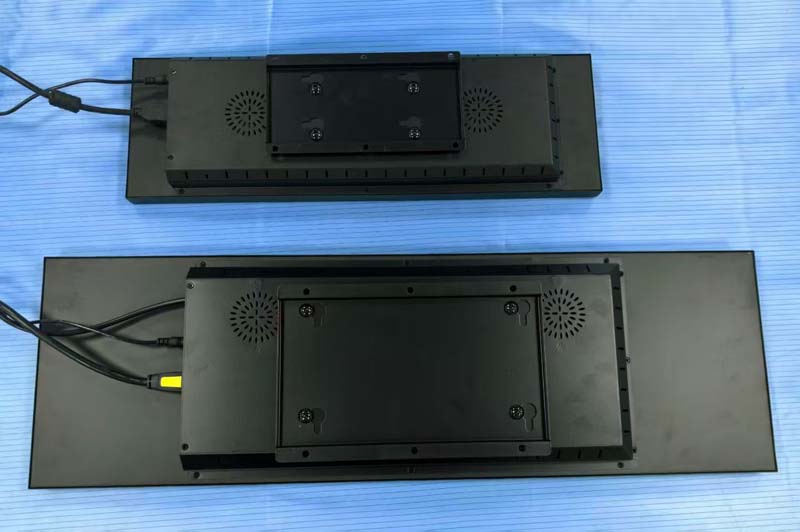
Architectural fit. Retrofits are the dominant procurement mode. The bar display is dimensioned to replace an existing LED matrix sign in the same cut-out, reusing the existing harness and mounting bosses where possible. Depth matters as much as width: a fully enclosed 28.9-inch bar unit typically needs 35–55 mm behind the front glass, which is tight against the window frame insulation.
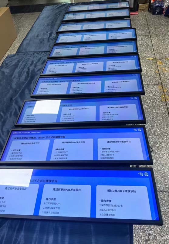
Content density. A 1920 × 480 canvas supports a permanent route/stop block plus a scrolling or tiled message region, a transfer-point icon row, an accessibility indicator, and a service-alert ticker — all at once. LED matrix signs cannot do colour, icons, or proportional type, and their character grid forces truncation that becomes a compliance problem when French strings run longer than English ones.
3. The Canadian Operating Environment
3.1 Cold start
Liquid crystal viscosity rises sharply below about −20 °C. Response time degrades from tens of milliseconds to seconds, contrast falls, and at −30 °C an unheated panel can display a smear for several minutes after power-up. For a bus pulling out of a Winnipeg yard at 05:30 in January, that is an unacceptable failure mode — the sign is unreadable precisely when the first riders board.
The standard remedy is an integrated heater: an indium tin oxide (ITO) film or a resistive heater plate behind the panel, sized at 20–40 W for a 28.9-inch unit, controlled by an NTC thermistor on the panel back surface. The controller strategy matters more than the heater wattage. A staged profile — full heater power below −10 °C with the backlight inhibited or driven at low duty, then a gradual backlight ramp as the panel reaches 0 °C — avoids the two common field failures: thermal shock cracking the panel from a cold-start backlight surge, and unnecessary heater cycling that shortens LED driver life. Target warm-up is under 120 seconds to a readable image at −30 °C, and full specification compliance by −20 °C.
3.2 Solar gain and heat soak
The opposite extreme is more damaging. A bus parked facing south in July with the interior at 45 °C can push the surface of a windshield-mounted sign past 70 °C, and the panel's own backlight adds 15–25 W of internal load inside a sealed enclosure. Panel selection must therefore be driven by the nematic isotropic transition temperature (Tni), not just the ambient operating range. Panels rated Tni ≥ 100 °C retain contrast and avoid permanent alignment-layer damage under these conditions; general-purpose panels rated to 60 °C ambient will fail within one or two summers.
Backlight derating is the second lever. White LEDs lose output and shift colour over life, and the rate roughly doubles for every 10 °C of junction temperature rise. A firmware thermal foldback curve that reduces luminance by 30–40% at internal temperatures above 65 °C preserves both legibility and the L70 lifetime target — typically 50,000 hours at 70 °C ambient for a well-derated design.
3.3 Corrosion and moisture
Canadian road maintenance uses chloride brine and rock salt in volumes that produce aggressive salt fog on the rear body and wheel arches. Exterior and door-side signs need a die-cast or extruded aluminium housing with a conversion coating and a powder coat rated to ASTM B117 salt spray exposure, stainless fasteners, and no dissimilar-metal contact points that can galvanically corrode. Ingress protection alone is not sufficient: a fully sealed enclosure that experiences daily temperature swings will breathe moisture through its gasket and then condense it on the coldest surface — usually the inside of the cover glass. A Gore-type ePTFE vent equalises pressure without admitting liquid water, and a desiccant pack or a low-power anti-fog heater film on the cover glass handles the residual.
3.4 Vibration and mechanical duty
Bus duty cycles are harsher than truck duty in one respect: constant stop-start, door slam, and curb strike. SAE J1455 random vibration profiles are the appropriate reference for interior equipment mounted on body panels. Practically, this means the panel must not be supported on its corners alone; a full-perimeter or continuous rear chassis with a compliant gasket distributes the load, and all connectors need positive-locking latches rather than friction-fit. Cable routing should never place a rigid harness in tension against the LVDS connector — the single most common field failure in first-generation transit LCD retrofits.
3.5 Electrical environment
A transit bus is a 24 VDC system with a noisy ground. The display's power stage should accept 9–36 VDC continuously, survive cranking dips to 6 V without rebooting, tolerate reverse polarity, and pass the ISO 7637-2 pulse set including the load-dump transient. Ignition-sense input is essential: the display must enter a standby state below 2 W when the bus is keyed off, and wake in under two seconds on ignition so the sign is live before the doors open. Inrush current must be limited — a dozen displays on one circuit, each drawing a 10 A surge into bulk capacitance, will trip breakers that were sized for LED signs drawing a fraction of that.
4. Optics and Sunlight Readability
Interior displays compete with window glare; exterior destination signs compete with direct sun. The two cases need different treatments.
For interior header signs, 700–1,200 cd/m² with an anti-glare cover glass (3–7% haze) and a matte bezel is generally sufficient, provided the display is tilted 5–10° downward to move the specular reflection of the windows out of the rider's line of sight. Optical bonding — laminating the cover glass to the panel with an index-matched adhesive — eliminates the internal air gap that otherwise produces a double reflection and a visible "ghost" image under bright window light. Bonding also improves contrast under high ambient and mechanically stiffens the stack.
For behind-windshield signs, luminance needs to exceed roughly three to five times the ambient reflected luminance of the glass to hold contrast. That means 2,000–5,000 cd/m², high-Tni panels, and a genuine anti-reflective coating (reflectance below 0.5%) rather than an anti-glare etch. Dimming must be flicker-free — DC dimming or PWM above 20 kHz — because low-frequency PWM at high brightness produces visible banding to the eye and severe artefacts in the CCTV and driver-monitoring cameras now common on Canadian buses.
Ambient-light-sensor-driven auto-dimming is not a luxury. A sign running at full 1,000 cd/m² at night is a glare hazard for the driver and a nuisance for riders in the front rows; the same sign at 30% output in daylight is unreadable. A six-point dimming curve referenced to an outward-facing lux sensor gives predictable behaviour and reduces LED thermal load overnight.
5. Bilingual Content and Accessibility Compliance
This is where Canadian deployments diverge most sharply from US ones, and where a bar display's pixel budget is genuinely tested.
French text expansion. French translations of English transit strings routinely run 15–25% longer — "Next stop" becomes "Prochain arrêt", "Transfer to Line 1" becomes "Correspondance vers la ligne 1". A layout that truncates or auto-scrolls a single line will fail bilingual requirements in Quebec under the Charter of the French Language, and will fail federal Official Languages Act expectations on federally regulated services. The practical answer is to design the default layout for the longer string, use a proportional typeface with a real French glyph set (accents, œ, guillemets), and define a deterministic truncation-and-marquee policy in firmware rather than letting the content author's character count decide. A common pattern is side-by-side EN/FR zones in the stop-information band, with a shared graphic lane for route colour and accessibility icons.
Accessibility regulation. Ontario's Integrated Accessibility Standards Regulation under the AODA, and the Canadian Transportation Agency's Accessible Transportation for Persons with Disabilities Regulations, both push toward information that is available in more than one sensory channel. For a display that means: high contrast (7:1 for text is a defensible target, above the 4.5:1 web minimum), minimum character heights scaled to viewing distance, no reliance on colour alone to convey route identity, and synchronisation with the audio next-stop announcement so visual and audible cues fire together. Text-only LED signs cannot meet the contrast or colour-independence requirements; a full-colour LCD can, but only if the content management system is designed to enforce them.
Symbols and pictograms. Wheelchair, stroller, and bike-rack indicators should be vector assets rendered at the panel's native resolution, not bitmap imports. At 0.37 mm pixel pitch, a 16 × 16 icon is 6 mm across and effectively invisible from a standing rider's position.
6. Integration Architecture
The display is one node in the onboard network, and its usefulness is bounded by what it can consume.
- Vehicle data: SAE J1939 over CAN for odometer, door status, and speed; a discrete ignition line; and where available, an RS-485 or Ethernet link to the CAD/AVL unit for next-stop triggers and schedule adherence.
- Content distribution: GTFS and GTFS-Realtime feeds staged at the depot, with the vehicle holding a local cache so a lost cellular link does not blank the sign. APTA's TCIP profiles remain the reference model for transit data interfacing in North America.
- Video and graphics: LVDS or eDP internally, HDMI or DisplayPort for engineering access, with an EDID that reports the native bar resolution so source devices do not letterbox.
- Management: outbound-only telemetry for luminance hours, internal temperature history, heater duty cycle, and fault codes. A fleet of 400 buses generates enough display telemetry to predict LED end-of-life and panel degradation before riders notice dimming.
Security hygiene belongs in the specification, not the afterthought. Signed firmware images, secure boot, no shared default credentials, and a documented patching path for the onboard OS are now baseline expectations for any device with an Ethernet port on a transit vehicle.
7. Qualification and Certification Path
A Canadian bus display should be qualified against a defined matrix rather than a single "automotive grade" claim:
| Domain | Reference |
|---|---|
| Product safety | CSA C22.2 No. 62368-1 / UL 62368-1 |
| EMC (Canada / vehicle) | ICES-003; UNECE Regulation No. 10 where vehicle-level approval applies |
| Electrical transients | ISO 7637-2, ISO 16750-2 (load dump, cranking, reverse polarity) |
| Climatic | IEC 60068-2-1 (cold), -2 (dry heat), -30 (damp heat cyclic), -52 (salt mist) |
| Vibration / shock | SAE J1455; IEC 60068-2-27 |
| Ingress / impact | IEC 60529 (IP), IEC 62262 (IK) |
| Flammability | CMVSS 302; UNECE Regulation No. 118 for M2/M3 interior materials |
| Ergonomics | ISO 9241 legibility guidance; ISO 15008 visual presentation principles |
Design verification on a new bar display typically runs 12–16 weeks: a thermal cycling profile from −40 °C to +85 °C with operational checkpoints at the extremes, a 500-hour damp-heat soak, salt fog exposure, random vibration to J1455, and an EMC sweep. Highly accelerated life testing is worth the added month for a new enclosure design, because condensation and connector fretting failures surface there far more cheaply than in a winter field trial.