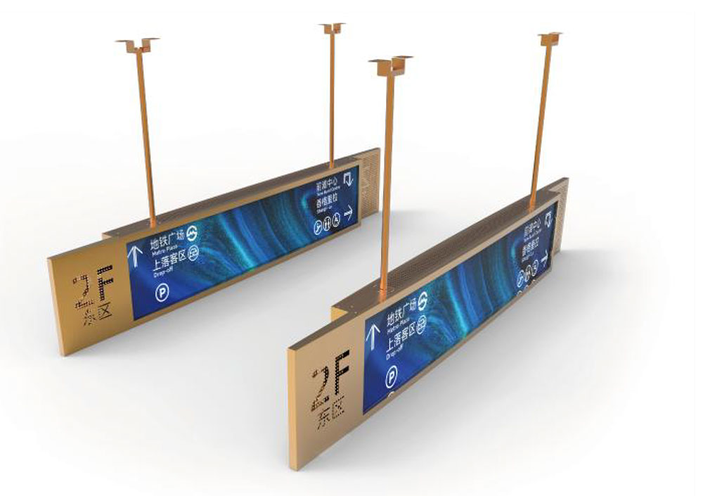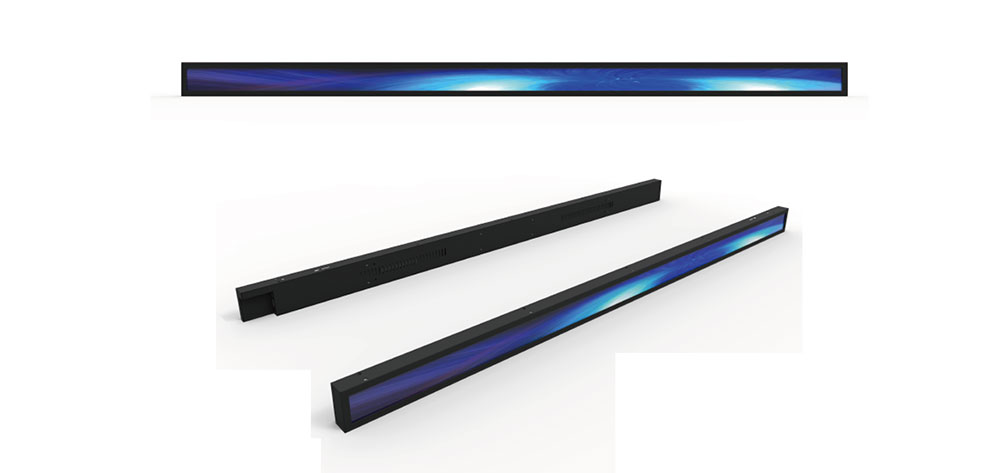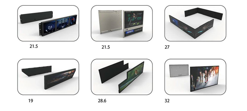
Bus operators face a deceptively simple display problem. The information that passengers actually need — the route number, the destination, the next stop, the transfer point, the platform — is short, wide, and highly repetitive, yet it must be legible from thirty metres away in direct sunlight, in rain, through a scratched plastic window, on a vehicle that vibrates, heats up, and runs fourteen hours a day. Conventional 16:9 panels are a poor geometric fit for this job: a wide-format module mounted in a destination header leaves most of the screen height unused, while a portrait module wastes width that the header simply does not have. Stretched LCD displays — bar-type or "ultra-wide" TFT modules with aspect ratios from roughly 3:1 to 8:1 — were developed specifically to close that gap. This paper examines what makes a stretched LCD suitable for bus route information and onboard signage, how the optical and mechanical specifications interact with the bus environment, and where the engineering pitfalls lie.
Why the Geometry Matters More Than the Resolution
A bus destination header is typically 900–1600 mm wide and 120–200 mm high, giving a usable aspect ratio between 6:1 and 10:1. A cut-to-fit stretched panel built to 37.5 inches diagonal at 16:1.9, or 28.8 inches at 16:3, sits inside that envelope almost exactly. The practical consequences are worth spelling out:
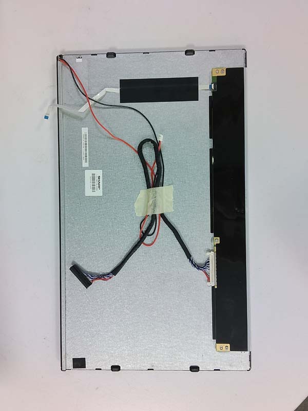
- No letterboxing. A native 16:9 panel forced into a header must either crop content or display black bars, both of which reduce effective brightness per unit area and look unfinished to passengers.
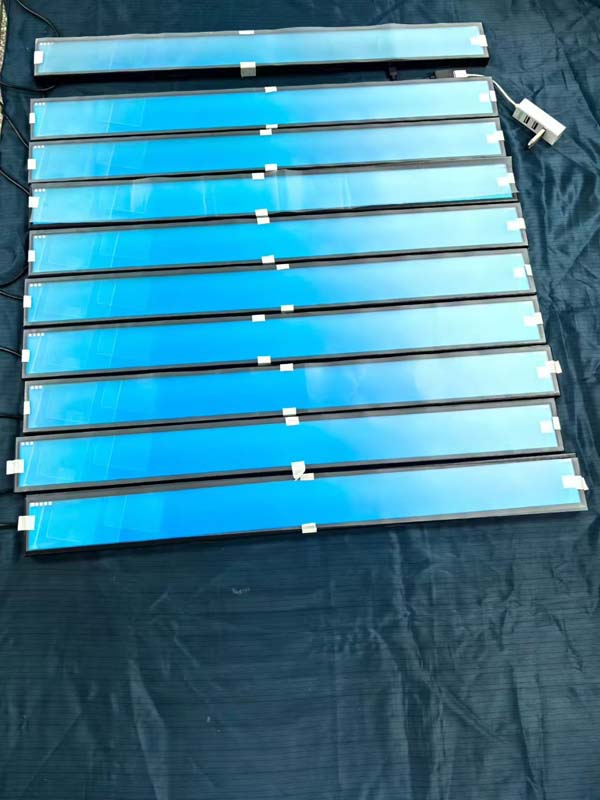
- Fewer panels, fewer seams. One 1200 × 180 mm stretched module replaces two or three small square panels with visible bezel gaps between them — a real maintenance benefit, since each seam is a place where moisture, dust, and vibration fatigue concentrate.
- Better thermal behaviour. A stretched panel of the same width but one-third the height dissipates heat over a smaller area, which is a drawback, but it also presents a much smaller solar collection area through the front glass. In practice, header-mounted stretched displays run cooler than large 16:9 panels behind the same windscreen, provided the backlight design is sound.
- Content design freedom. A 1920 × 240 or 1920 × 480 canvas maps naturally onto the "route number | destination | via points | next stop" information hierarchy that transit authorities already use.
Optical Performance: The Sunlight Readability Problem
Bus signage is a worst-case optical environment. In summer, the front header of a stationary bus can see illuminance well above 100,000 lux, and the passenger-facing interior signs compete with windows that are themselves a glare source. Three specifications govern whether the display survives this:
Luminance
Interior next-stop signs generally require 500–700 cd/m² to remain readable against window glare. Exterior-facing destination signs and any display mounted behind untinted glass should target 1000–1500 cd/m², and units intended for direct sun exposure on the header should reach 2000 cd/m² or higher. It is important to specify sustained luminance after thermal stabilisation, not the instantaneous peak measured at 25 °C. A backlight that produces 1500 cd/m² cold but sags to 900 cd/m² after two hours in a 60 °C enclosure has not met the requirement.
Contrast and Reflection
Contrast ratio figures quoted in dark-room conditions are close to meaningless here. The governing parameter is the ratio of emitted luminance to reflected ambient luminance. Two measures control it: an anti-glare (AG) surface treatment — typically an anti-reflective or low-haze AG coating, sometimes combined with a circular polariser — and, more importantly, optical bonding of the cover glass or touch panel to the LCD cell. Bonding eliminates the internal air gap that otherwise produces double reflections and internal fogging under humid conditions. For exterior signage, a bonded stack with an AR-coated front surface can raise perceived contrast by a factor of two or three compared with an unbonded, air-gap assembly at the same backlight power.
Viewing Angle and Uniformity
Passengers view next-stop signs from below and from the side, often at 60–70 degrees off-axis. IPS-type or equivalent wide-view technology is effectively mandatory for interior signage; TN-based stretched modules should be avoided regardless of cost advantage. Brightness uniformity across a 1200 mm bar is another frequently neglected point — a 60/40 split between centre and ends is visible to any passenger and reads as a quality defect. Specify 75% minimum uniformity (9-point measurement) and require the supplier to report it on the actual production batch.
| Parameter | Interior next-stop sign | Exterior destination sign |
|---|---|---|
| Typical size | 28.8"–37.5" bar type | 37.5"–48" bar type |
| Sustained luminance | 600–800 cd/m² | 1500–2500 cd/m² |
| Contrast (with bonding) | ≥ 1000:1 | ≥ 1500:1 |
| Uniformity (9-point) | ≥ 75% | ≥ 70% |
| Operating temperature | −20 °C to +70 °C | −30 °C to +80 °C |
| Ingress protection | IP54 front | IP65 / IP67 front |
| Interface | LVDS / eDP | LVDS, extended cable runs |
Environmental and Mechanical Qualification
The bus environment is closer to off-highway industrial than to consumer electronics. A credible stretched display for onboard signage should be qualified against the following, and the test reports — not merely a compliance statement — should be requested:
- Temperature and humidity: operational −30 °C to +80 °C for exterior units, with cold-start capability at −30 °C; storage to +85 °C; damp-heat cycling per IEC 60068-2-30. Note that liquid-crystal response time degrades sharply below −20 °C, so specify a heater film or backlight pre-heat strategy if the vehicle operates in cold climates, and require the supplier to state the actual switching time at the low-temperature limit.
- Vibration and shock: random vibration profiles representative of body-mounted and engine-bay-adjacent locations, typically 5–500 Hz at 1.5–3 g RMS depending on mounting point, plus half-sine shock of 30 g / 18 ms. Long, thin modules are mechanically vulnerable at the centre of the bar; the chassis and backlight support structure must be designed for it, not the glass.
- Automotive EMC: ECE R10 (E-mark) for the vehicle-level approval, supported by component-level testing to ISO 11452-2/4 (radiated immunity), ISO 7637-2 (transient conduction on supply lines), and CISPR 25 (emissions). Bus 24 V systems produce load-dump and cranking transients that will destroy an unprotected display driver board.
- Fire safety of materials: ECE R118 governs flammability of interior materials in buses; enclosure plastics and adhesives should be specified accordingly, and rail-adjacent deployments may instead require EN 45545-2 classifications.
- Optical durability: abrasion resistance of the front surface (pencil hardness, steel-wool test), resistance to common cleaning agents and disinfectants — a point that became far more prominent after 2020 — and UV stability of the polariser and adhesives for exterior units.
Electronics, Interfaces, and System Integration
A stretched panel is one component in a passenger information chain that runs from the depot management system, through an onboard controller, to the display. Integration choices made at the display level determine how much of that chain the operator has to re-engineer.
Signal Interface and Cable Length
Most stretched modules use LVDS or eDP. LVDS remains the pragmatic default in bus signage because it tolerates the 2–5 m cable runs typical between a controller in the electrical cabinet and a display in the header, and because locking, vibration-resistant connectors are widely available. eDP offers higher bandwidth for 4K-class bars but is more sensitive to cable quality and connector retention. Where several bar displays must show synchronised content — for example, a dual-sided header or a curved interior strip — a daisy-chain (LVDS loop-through) topology reduces harness count substantially.
Control and Diagnostics
Transit fleets are managed, not merely operated. A display that reports its own health is worth considerably more than one that simply goes dark. Relevant capabilities include an I²C or RS-485 control channel for backlight dimming, a UART service port, on-board temperature and backlight-current telemetry, and support for the vehicle's CAN bus or an Ethernet backbone using protocols such as JT/T 808 or the operator's proprietary vehicle bus. Ambient-light-sensor-driven auto-dimming is not a luxury: it reduces night-time glare for the driver, extends backlight life, and cuts power consumption across a fleet of several hundred vehicles.
Backlight Architecture
Direct-lit LED backlights with local dimming are increasingly practical in bar formats and deliver two benefits: deeper blacks for advertising content and the ability to run at reduced power in dim conditions. For pure route text on a white or amber background, edge-lit designs remain cost-effective and thinner, but they struggle with uniformity on long modules. Whichever topology is chosen, require a documented LED lifetime figure at the operating temperature — L70 at 50,000 hours is a reasonable floor for fleet use — and confirm that the driver electronics include open/short detection per string so a single LED failure does not extinguish a segment of the bar.
Content, Legibility, and Standards Compliance
Display hardware cannot rescue poorly designed content, and the reverse is equally true. Transit authorities generally publish signage guidelines covering minimum character heights, contrast ratios, and the treatment of route numbers versus destination text. A stretched display gives the content designer continuous horizontal space, which should be used for information hierarchy — a large route number at the leading edge, destination text at a consistent x-height, via points in a secondary weight — rather than for cramming in additional text. Practical rules that hold up in service:
- Minimum cap height of roughly 1/200 of the intended reading distance; for a 25 m reading distance, that is around 125 mm, which usually forces a two-line or scrolling treatment on a 180 mm bar.
- Static text wherever possible; scrolling and paging increase dwell time and slow comprehension, and should be reserved for overflow content.
- High contrast pairings only — white on black, amber on black, or black on white — and never coloured text on a coloured background, which suffers badly when the backlight ages.
- Explicit failure behaviour: a defined fallback state showing at least the route number if the content feed drops, rather than a blank screen or an error dialog.
Regulatory obligations also attach to the information itself. Accessibility requirements in many jurisdictions mandate visual and audible next-stop announcements, and the visual element is increasingly delivered by these displays; the display must therefore be capable of being driven from the same source as the audio announcement system, with synchronisation guaranteed. Where displays are used for advertising alongside route information, operators should confirm that the advertising content controller cannot pre-empt the route information layer — a layered rendering architecture with the transit information in the top layer is the sound engineering answer.
Reliability, Service Life, and Total Cost of Ownership
Fleet procurement is decided on total cost of ownership, not unit price. The dominant cost drivers for onboard signage are field failures, access time for replacement, and premature obsolescence of the module. Design measures that pay back:
- Sealed, connector-side service access. Header-mounted displays are difficult to reach; a design where the harness connectors and controller board are accessible from the interior side without removing the whole assembly can halve labour time per service event.
- Long-term module availability. Transit vehicles have 12–15 year service lives; a display module with an 18-month market window creates a spares problem immediately. Require a written longevity commitment, typically five to seven years of production availability plus a stated last-time-buy window.
- Consistent firmware and configuration management. Fleet-wide parameter changes — dimming curves, content layouts, language sets — should be deployable over the vehicle network, not by physical access to each display.
- Documented MTBF and field failure data. A supplier who cannot produce field return rates from comparable transit deployments is asking the operator to underwrite their learning curve.
Selection Checklist
When evaluating stretched LCD displays for bus route information and onboard signage, the following questions separate a suitable module from a specification sheet that merely looks suitable:
- What is the sustained luminance after 60 minutes at maximum operating temperature, measured on the production unit?
- Is the front stack optically bonded, and what is the measured reflectance of the finished assembly?
- What is the low-temperature response time at −30 °C, and does the design include heating?
- Which EMC and environmental test reports exist, to which standards, and at which revision?
- What is the vibration qualification level, and at which mounting point was it derived?
- How is the backlight monitored, and what happens to the image when a single LED string fails?
- What is the committed production lifetime, and what is the spares strategy beyond it?
- Can the display accept firmware and configuration updates over the vehicle network?
Stretched LCD displays are not simply wide panels; they are a distinct mechanical and optical discipline, and the failure modes that matter in a bus — delamination at the ends of a long bonded stack, non-uniform backlight ageing, cold-start response, transient-induced driver failure — are specific to the format. Specifying against sustained performance rather than headline numbers, and requiring evidence rather than declarations, is what turns a promising display into fourteen years of dependable signage.
KEYWORDS: stretched LCD display, bus route information display, onboard signage, high brightness bar LCD, passenger information system