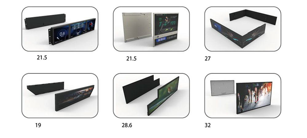
A display in a passenger car, a city bus, a locomotive cab or a roadside charging kiosk is not a consumer monitor with a different bezel. It is a mechanical structure, a thermal system and an electrical interface that must all remain inside specification for a service life measured in years, across duty cycles that no laboratory bench ever reproduces exactly. The three requirements that decide whether a transportation display survives are vibration and shock, operating temperature, and the signal interface that connects the panel to the host. Each one is usually specified separately in a datasheet; in the field they interact, and that interaction is where most field failures originate.
Vibration and Shock: Designing for a Moving Platform
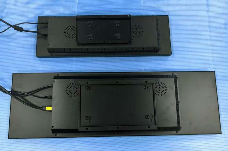
Transportation vibration is not a single phenomenon. A diesel engine at idle produces a narrow-band excitation near its firing frequency. Road surfaces produce broadband random vibration concentrated below 500 Hz. Rail joints and switches produce repeated high-amplitude shock transients, and a display bracket that rings at 80 Hz will fatigue an FPC connector within months on a locomotive that a road-vehicle profile would never stress at all.
Qualification is therefore defined by the platform, not by a generic "vibration resistant" claim. The profiles most often written into transportation display specifications include:
| Standard | Scope | Typical test content |
|---|---|---|
| IEC 60068-2-6 | Sinusoidal vibration | Frequency sweep, e.g. 10–500 Hz, 1–2 g, one cycle per axis |
| IEC 60068-2-27 | Mechanical shock | Half-sine pulses, typically 30–100 g, 6–11 ms |
| ISO 16750-3 | Road vehicles | Random vibration by mounting location, engine and wheel excitation |
| SAE J1455 | Heavy truck / off-highway | Random vibration and shock combined with thermal cycling |
| EN 50155 / IEC 61373 | Rail rolling stock | Random vibration and shock by equipment class (body, bogie, axle) |
| MIL-STD-810, Method 514/516 | Ground and vehicular | Tailored random vibration and functional shock |
Two design details matter more than the headline test level. The first is resonance mapping. A display assembly should be characterized from 10 Hz to 500 Hz or higher under sine sweep to identify where its first mode sits. If the first mode of the panel-plus-bracket mass lands inside the excitation band of the platform — commonly 20–200 Hz for road and rail body mounting — the assembly will amplify rather than attenuate input, and the amplification factor at resonance can reach ten or more. Stiffening the bracket, shortening the cantilever, or adding a rear structural frame moves the mode upward; adding mass in the wrong place moves it down and makes things worse.
The second is the failure path. Panels rarely crack. What fails is the interconnect: the ZIF contact at the FPC tail, the solder joint at the LED string connector, the touch flex adhesive, the screw that backs out under repeated shock. Design rules that consistently improve field life include mechanically retaining the FPC tail with a clamp or adhesive bead rather than relying on the ZIF latch alone, routing flex cable with a service loop so that vibration is absorbed by the loop rather than by the contact, specifying thread-locking or captive fasteners with defined torque, and avoiding unsupported cable spans longer than roughly 100 mm without an anchored tie. Where the platform includes high-amplitude shock — rail switches, off-highway equipment — a shock-isolating gasket or elastomeric mount can be appropriate, provided the resulting low-frequency mode does not worsen the random-vibration response.
Temperature: The Range Is Only Half the Requirement
A transportation display is usually specified for operation from −30 °C or −40 °C to +70 °C or +85 °C, with storage extending wider. Those numbers are necessary but not sufficient, because the panel does not experience ambient temperature — it experiences the sum of ambient, solar load and its own backlight dissipation.
A high-brightness display intended for sunlight readability may consume 15 to 40 W in the backlight alone, most of which becomes heat inside a sealed enclosure. In a closed dashboard housing at 70 °C ambient, the liquid crystal layer itself can sit 15 to 25 °C above ambient unless heat is deliberately conducted away from the panel rear. This is why high-brightness designs must be treated as thermal designs: a metal back plate or chassis that conducts LED heat to the enclosure wall, thermal interface material between the LED bar and the frame, and a housing surface that can dissipate the load. Without that path, the panel derates — luminance drops, contrast shifts, and the LED junction temperature accelerates lumen depreciation far faster than the datasheet's lifetime curve suggests.
At the cold end the physics reverses. Liquid crystal viscosity rises sharply, response time lengthens from tens of milliseconds to several hundred, and the display may appear to smear or briefly retain the previous image. Below roughly −20 °C, many standard TN and IPS panels become marginal without a heater. Options include an ITO transparent heater film on the front glass, a resistive heater bonded to the rear polarizer, or a heated front lens. Whichever is used, the specification should state heat-up time from cold soak to full luminance and full response — for example, 90% luminance within five minutes from −40 °C — rather than simply claiming operation at that temperature.
Thermal cycling and humidity create a third class of problem. Repeated −40 °C to +85 °C transitions fatigue solder joints and delaminate optical bonding if the adhesive and the glass have mismatched coefficients of expansion. Condensation inside a housing that is not breathable will fog the inner surface of the cover lens; a breathable membrane vent, a desiccant, or full optical bonding between panel and lens addresses it. For automotive programs, the component grade sets the baseline expectation: AEC-Q100 Grade 2 for −40 °C to +105 °C ambient electronics and AEC-Q104 for multi-chip modules. For rail, EN 50155 defines temperature classes (T1 through TX) that widen beyond the nominal −25 °C to +55 °C cabinet class, and OT4 or ST2 classes are common where equipment sees the outside air.
Interface Requirements: Signal Integrity Over Real Cable Lengths
The interface question in transportation is almost never about bandwidth. It is about distance, connector robustness, and electromagnetic environment. A panel that works with a 150 mm flex on a bench may fail with a 1.5 m harness routed past a motor drive.
| Interface | Practical reach | Where it fits |
|---|---|---|
| RGB parallel | < 100 mm, board-to-board | Small panels inside the same housing as the host |
| LVDS (single/dual) | 0.5–3 m with shielded twisted pairs | Mainstream transportation TFTs, mature and well supported |
| eDP | 1–3 m | Higher resolution panels, lane-count scaling, embedded timing controller |
| MIPI DSI | < 300 mm typical | Short internal links, mobile-derived panels |
| FPD-Link III / GMSL | 10–15 m over coax | Serdes links where the display sits far from the host, e.g. mirror-replacement or remote cluster |
For LVDS and eDP the controlling variables are differential impedance (100 Ω nominal), pair-to-pair skew, and shielding. Transportation harnesses often run alongside high-current switching loads, so the cable shield must be terminated to chassis at the connector shell with a low-impedance bond, and the ground reference should be planned as a single controlled return rather than left to whatever the harness provides. Twisted-pair construction with an overall foil or braid is the norm; unshielded ribbon over more than a few hundred millimetres is a reliability risk, not a cost saving.
Connector choice carries equal weight. Fine-pitch ZIF connectors with a locking bar are adequate inside a sealed module; for external or serviceable connections, positive-latch board-to-wire connectors with strain relief and keyed housings are preferable. Every connector should be specified with a mating cycle rating, an operating temperature range matching the panel, and a defined contact plating for the humidity class involved.
On the electrical side, transportation programs usually require EMC performance to CISPR 25 (vehicles) or EN 50121 (rail), immunity testing to ISO 11452, and ESD testing to ISO 10605 rather than the consumer IEC 61000-4-2 profile, because the discharge network and levels differ. Practical measures include series termination or common-mode chokes on clock pairs, spread-spectrum modulation of the display clock where the timing controller allows it, and a shielded backlight driver harness. Power sequencing also matters: panel logic and backlight rails must come up and go down in the order the panel specifies, with inrush limiting so that a cold-start at −40 °C, where supply impedance is highest, does not brown out the host. Dimming should use a PWM frequency high enough to avoid visible flicker and beat patterns with camera-based systems in the vehicle — above roughly 2 kHz, or a hybrid PWM-plus-analog scheme. Where the display includes diagnostics, a bidirectional control bus (I²C, SPI or CAN) that reports backlight status, temperature and fault codes materially reduces field-diagnosis cost.
Specifying the Whole System
A transportation display specification that stands up to review lists, at minimum: the vibration and shock profile with the mounting location it corresponds to; the resonant frequencies measured on the actual assembly; the operating and storage temperature range with the self-heating allowance stated separately from ambient; heat-up time from cold soak; luminance derating versus temperature; the interface type with cable length, impedance and connector part number; EMC and ESD standards with test levels; ingress protection; and the validation plan that combines these — thermal cycling under vibration, power cycling at temperature extremes, and humidity soak. Tested separately, each parameter can be passed. Tested together, they reveal whether the design was actually engineered or merely assembled.
KEYWORDS: transportation LCD display, high brightness LCD, wide temperature display, vibration resistant display, LVDS interface