Introduction
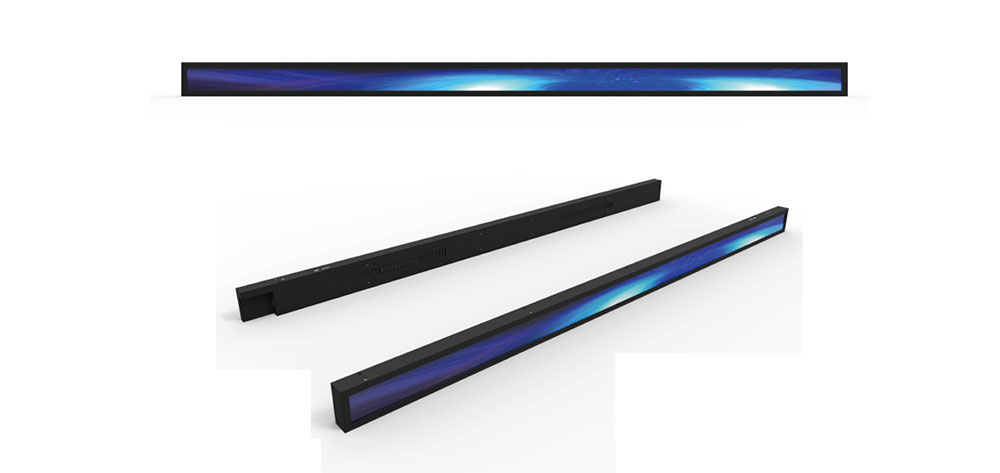
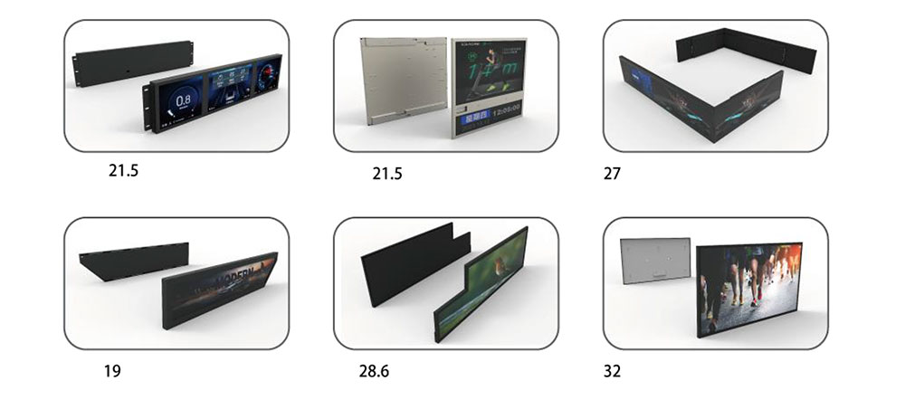
Wide format display modules have become a defining component of modern embedded systems, reshaping how information is presented in vehicles, industrial control panels, medical instruments, kiosks, and public transportation. Unlike conventional 4:3 or 16:9 panels, wide format modules use elongated aspect ratios such as 16:9, 24:9, or even ultra-stretched formats like 32:9 and 1000:230. These proportions allow engineers to fit rich visual content into narrow mechanical envelopes, delivering information-dense layouts where physical space is limited but visual clarity is critical.
At HITULCD, we design high-brightness wide format modules specifically for embedded deployment, where reliability, sunlight readability, thermal stability, and electromagnetic compliance are non-negotiable. This white paper examines the engineering considerations behind wide format display modules for embedded applications, with particular attention to FCC testing and electromagnetic compatibility, which is often the deciding factor between a prototype and a shippable product.
Why Wide Format Displays Suit Embedded Systems
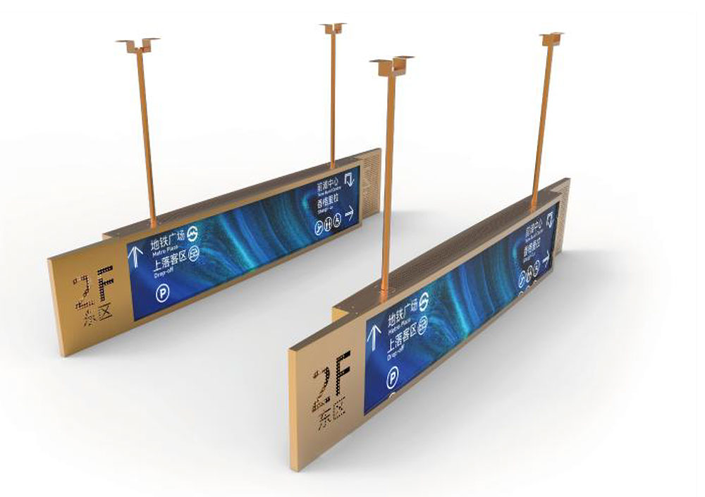
Embedded systems frequently operate within constrained mechanical footprints. A digital shelf edge label, an automotive instrument cluster, an elevator status bar, or a factory line indicator all share the same challenge: a long, shallow opening that a standard rectangular panel cannot fill efficiently. Wide format modules solve this by matching the display geometry to the mechanical aperture.
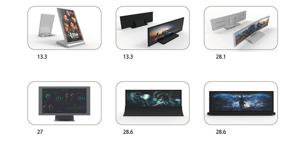
Beyond form factor, wide aspect ratios improve information ergonomics. A stretched display can present a continuous status bar, a scrolling data ribbon, or side-by-side content regions without forcing the user to scan vertically. In driver-facing automotive applications, this reduces cognitive load and glance time. In industrial HMI panels, it allows process values, alarms, and trend graphs to coexist in a single glanceable strip.
Core Technical Characteristics
High Brightness and Sunlight Readability
Embedded displays are rarely used in controlled lighting. Outdoor kiosks, transportation signage, and vehicle dashboards demand luminance levels well above the 250 to 350 nits typical of consumer panels. HITULCD wide format modules are engineered from 800 nits up to 2500 nits, with optical bonding and anti-reflective treatments that preserve contrast under direct sunlight. High brightness also enables automatic dimming schemes that conserve power in low-light conditions while remaining readable at midday.
Wide Operating Temperature Range
Embedded modules must survive environments that consumer electronics never see. Our wide format panels support extended temperature operation from -30°C to +85°C, using wide-temperature liquid crystal fluids and heater options for cold-start scenarios. Thermal management is coordinated with the backlight driver to prevent luminance drift across the operating envelope.
Interface Flexibility
Wide format modules ship with interface options tailored to embedded controllers, including LVDS, MIPI-DSI, and eDP for higher resolutions. For simpler integrations, RGB and SPI interfaces remain available on smaller modules. Matching the interface to the host SoC reduces bridge chips, lowers bill-of-materials cost, and simplifies EMI mitigation, which we will return to in the FCC discussion.
Long Lifecycle and Supply Stability
Embedded programs often run for seven to ten years. HITULCD commits to long-term availability of wide format modules, with controlled revision management so that a design certified today does not require recertification because of an unannounced panel change.
FCC Testing for Wide Format Embedded Modules
Any electronic product marketed or operated in the United States that contains a digital device must comply with FCC Part 15 rules governing unintentional radiators. A wide format display module, with its long flex cables, high-speed serial links, and switching backlight converter, is a meaningful source of radiated and conducted emissions. FCC testing is therefore central to the productization of any embedded display, and it should be planned from the earliest design stage rather than treated as a final hurdle.
Understanding FCC Part 15: Class A vs Class B
The FCC divides digital devices into two classes. Class A covers equipment intended for commercial, industrial, or business environments. Class B covers equipment intended for residential use and imposes stricter emission limits, roughly 10 dB tighter across the measured spectrum. A wide format module destined for a factory HMI may target Class A, while the same panel inside a consumer smart-home hub must meet Class B. Establishing the target class early determines the entire EMC design budget, because the additional headroom required for Class B directly influences filtering, shielding, and layout decisions.
Radiated Emissions
Radiated emissions testing measures the electromagnetic energy a device broadcasts into free space, typically from 30 MHz to 1 GHz, and up to 6 GHz for products with high-speed clocks. Wide format modules are particularly exposed here because their elongated geometry produces long signal traces and cables that behave as efficient antennas at specific frequencies. The primary offenders are:
- High-speed LVDS, MIPI, or eDP data pairs, whose harmonics can radiate strongly if impedance is poorly controlled.
- The pixel clock and its harmonics, which appear as sharp spectral peaks.
- The LED backlight boost converter switching node, a broadband noise source.
Mitigation begins at the module level. HITULCD applies controlled-impedance flex design, tightly coupled differential pairs, ground guarding along cable routes, and spread-spectrum clocking on the timing controller where the application permits. At the system integration level, integrators should keep the display flex short, terminate the cable shield to chassis ground, and avoid routing the flex across enclosure seams.
Conducted Emissions
Conducted emissions testing measures the noise a device injects back onto its power supply lines, generally across 150 kHz to 30 MHz. For embedded modules powered from a shared DC rail, the backlight converter and the panel logic supply are the dominant contributors. Input pi-filters, common-mode chokes on the supply entry, and adequate bulk and high-frequency decoupling on the module connector are the standard countermeasures. Because the wide format backlight often drives many LEDs in long strings, the converter operates at higher voltages and currents, making conducted noise suppression especially important.
The Pre-Compliance Advantage
Full FCC certification is performed at an accredited test lab, but discovering a failure at that stage is expensive and schedule-crushing. We strongly recommend pre-compliance testing during development using a near-field probe set, a spectrum analyzer, and a basic LISN for conducted measurements. Pre-compliance scans locate the offending frequency and, with a near-field probe, the physical source on the board or cable. This lets engineers correct problems while the design is still flexible, rather than after tooling and layout are frozen. In our experience, roughly eighty percent of first-pass emission problems on embedded display designs trace back to grounding of the display flex and decoupling of the backlight converter, both of which are cheap to fix early and painful to fix late.
Documentation and Marking
Most embedded display products fall under the FCC Supplier's Declaration of Conformity (SDoC) pathway for unintentional radiators. This requires the responsible party to maintain a test report demonstrating compliance, apply the appropriate FCC labeling, and include the required compliance statement in the product documentation. HITULCD supplies module-level EMC characterization data to support our customers' system-level SDoC filings, shortening the path to a defensible compliance file.
Design Guidelines for Integrators
To streamline both performance and FCC testing, integrators of wide format modules should observe several practices. Route high-speed display pairs as tightly coupled differential traces over a continuous ground plane, and never allow the return path to cross a plane split. Keep the display flex as short as mechanically possible, and provide a low-impedance ground connection where the flex meets the host board. Place the backlight converter close to its input filtering and away from sensitive analog or RF circuits. Finally, plan the enclosure so that any metal chassis can serve as a shield, with clean grounding to the display frame. These measures improve image quality and dramatically reduce the risk of a late-stage FCC failure.
Conclusion
Wide format display modules unlock design freedom for embedded systems, matching the display to the mechanical aperture while delivering dense, glanceable information. But the same elongated geometry that makes them attractive also makes electromagnetic compliance a first-order design concern. Treating FCC testing as an integral part of the development process, from choosing the target emission class through pre-compliance scanning and disciplined grounding, is what separates a working prototype from a certified, shippable product. HITULCD combines high-brightness, wide-temperature wide format modules with EMC-aware engineering support, helping integrators bring compliant embedded displays to market with confidence.
KEYWORDS: wide format display modules, embedded applications, FCC testing, high brightness LCD, EMC compliance