Why Stretched Displays Exist
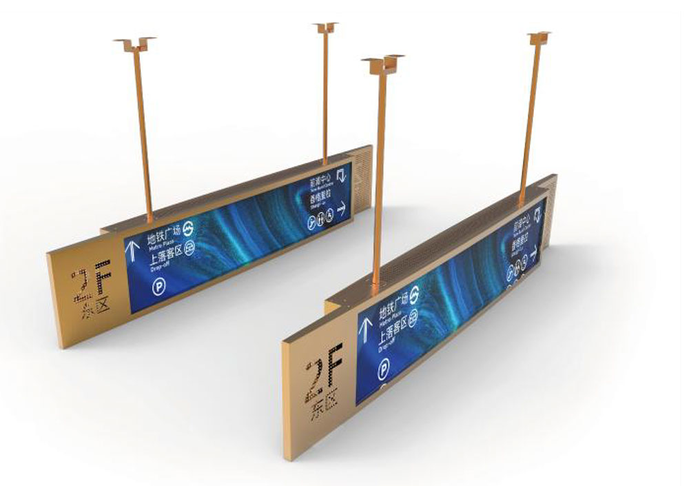
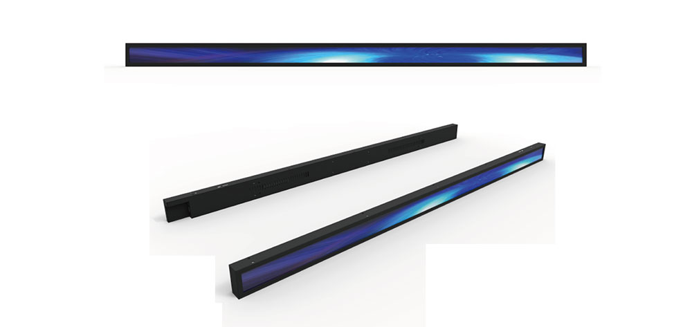
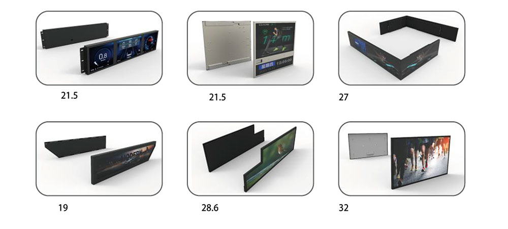
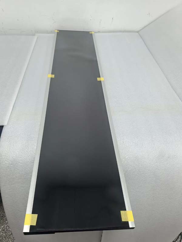
A bar type LCD module — also called a stretched, strip, or ultra-wide display — is a liquid crystal panel whose active area departs sharply from the 16:9 and 16:10 shapes that dominate consumer supply. Typical aspect ratios run from 16:3 and 8:1 up to 37:1 in the extreme, producing a thin horizontal band of pixels that fits into spaces a conventional panel physically cannot occupy: the top rail of a rack-mounted appliance, the two-centimetre strip above a vending machine's dispensing tray, the instrument cluster of a two-wheeler, the shelf-edge rail in a retail aisle.
The engineering consequences are not simply "a normal panel cut narrow." Every subsystem — glass generation, driver IC placement, backlight optics, flex routing, host interface, firmware — has to be re-examined. This guide walks through the four decisions that determine whether a bar type module integrates cleanly: size, resolution, interface, and the mechanical–thermal envelope around them.
Size: The Constraints Behind the Catalogue
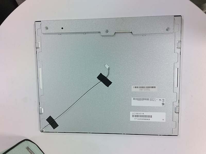
Bar type panels are cut from standard mother glass, so the available sizes are governed by how many strips can be yielded from a given substrate rather than by an idealised design intent. That is why the market clusters around a small set of diagonal sizes.
| Diagonal | Typical active area | Common aspect | Usual application |
|---|---|---|---|
| 3.9"–4.6" | ~100 × 25 mm | 4:1 | Wearables, handheld instruments, e-bike dashboards |
| 6.2"–6.9" | ~150 × 40 mm | 4:1 to 6:1 | POS terminals, taximeters, small kiosks |
| 8.8"–12.3" | ~220 × 60 mm to 290 × 90 mm | 3:1 to 4:1 | Automotive clusters, appliance fascias, shelf labels |
| 16.4"–19" | ~410 × 100 mm | 4:1 | Rack front panels, industrial HMI bars |
| 23.1"–28" | ~580 × 130 mm to 700 × 150 mm | 4:1 to 5:1 | Digital signage, transport information strips |
| 37"+ | ~900 × 100 mm | 9:1 and beyond | Metro carriage signage, long shelf rails |
Three practical notes on selecting a size. First, outline dimensions matter more than diagonal: a 12.3" bar from one vendor may have a different bezel width, flex exit position, and screw boss layout than a 12.3" bar from another, and those differences usually decide the mechanical design. Second, cut feasibility constrains custom sizes — asking for an arbitrary diagonal rarely produces an economically viable tooling quote, whereas selecting an existing glass and specifying custom cover glass, touch, and backlight is routine. Third, the flex tail is part of the size decision: on a 400 mm-wide module, a single bottom-exit FPC creates a voltage drop and routing problem that a dual-tail or side-exit design solves.
Resolution: PPI, Not Pixel Count, Is the Real Metric
Because bar panels are narrow, their pixel density is often surprisingly high even at modest total resolution. A 1424 × 280 strip over a 290 mm width delivers about 125 PPI — comfortable for text at 40 cm viewing distance. The same 1424 pixels spread over a 900 mm strip fall to roughly 40 PPI, where individual pixels become visible and anti-aliased fonts are essential.
Matching resolution to viewing distance
The working rule is that the minimum resolvable detail should be smaller than roughly one arcminute at the intended viewing distance. For a shelf-edge rail viewed at 1 m, 40 PPI is generous. For a handheld meter viewed at 30 cm, 150 PPI or better is needed to avoid visible stair-stepping on diagonal strokes.
The resolution traps
- Non-standard pixel clocks. Bar panels frequently use resolutions that no standard video mode covers, so the host must generate custom timings. Confirm the panel's minimum and maximum horizontal and vertical blanking before committing to a SoC, because some display controllers cannot produce the very short vertical blanking a shallow panel requires.
- Oversized total timing. Total horizontal timing (active + blanking) must stay within the interface's bandwidth. On single-channel LVDS at 65 MHz, a 1920-pixel-wide bar at 60 Hz is already at the limit; twin-channel LVDS or eDP becomes mandatory.
- Fractional scaling. If the host renders a 1080p framebuffer onto a 1920 × 540 panel, vertical halving produces uneven line weights and shimmer on motion. Render natively where possible.
- Row-adjacent artefacts. In very wide panels, gate-line resistance causes a slight brightness gradient across the strip. This is normal and specified as a uniformity figure; verify it against your acceptance criteria rather than discovering it at incoming inspection.
Interface Selection
The interface is usually determined by the host SoC, not the panel, but bar modules expose a few constraints worth checking early.
RGB parallel (TTL)
Still common on modules up to about 7" diagonal at 800 × 480 and below. Cheap, simple to bring up, and adequate for static content. Its weakness in bar applications is cable length: 24-bit RGB plus clock, DE, and HSYNC/VSYNC is roughly 28 conductors, and every one of them is a potential EMI radiator. Keep the flex under 150 mm and, if the panel sits on a separate board, expect to add series termination and a shielded FFC.
LVDS
The default for industrial bars from 7" to 28". Single-channel LVDS carries up to about 1366 × 768 at 60 Hz within a 65 MHz pixel clock; above that, dual-channel LVDS is required. Design notes: use 100 Ω differential routing, keep intra-pair skew under 10 mm and inter-pair skew under 30 mm, and place the LVDS connector as close to the SoC's transmitter as the mechanical design allows. For cable runs beyond roughly 500 mm, specify a shielded twisted-pair cable assembly rather than flat FFC.
MIPI DSI
Attractive on paper — four lanes replace twenty-eight wires — but two issues recur in bar designs. First, MIPI is a short-reach interface; anything beyond about 300 mm of flex needs a bridge or a redriver, which adds cost and a failure mode. Second, many industrial SoCs offer a limited number of DSI channels, and a bar display often competes with a camera or a second panel. Verify lane count and maximum per-lane bit rate against the actual resolution and refresh rate.
eDP
Increasingly offered on larger bars (23" and above) because it scales to high resolution with a small connector and supports embedded DisplayPort link training. It requires the host to read or hard-code the panel's link parameters; on industrial boards where EDID is not implemented, confirm the transmitter can be fixed to the correct lane count and rate.
SPI and MCU bus
Found on small bars under about 5", typically paired with an integrated GRAM controller. Refresh rate becomes limited by the serial bus, so these suit slowly changing content — gauges, status strips, labels — rather than video.
Backlight and Brightness
Bar modules are overwhelmingly specified for high brightness, because their typical homes — outdoor signage, appliance fronts, transport information — are lit environments. Values of 800 to 1500 cd/m² are routine; 2000 cd/m² appears in sunlight-readable variants.
Three consequences follow:
- Thermal load. LED backlights at high drive currents dissipate most of their electrical power as heat. On a narrow module the heat has very little area to escape through, so the rear chassis, not the front glass, is the thermal path. Specify a metal chassis or a graphite spreader, and verify the panel's maximum operating temperature with the backlight at 100% in the intended enclosure — not on an open bench.
- Driver design. Constant-current boost drivers are standard. Check the driver's input voltage range against the system rail, its ability to deliver the full string current at minimum battery voltage, and its dimming method. PWM dimming below about 200 Hz causes visible flicker in peripheral vision and interferes with camera-based systems; analogue or high-frequency hybrid dimming is preferable for machine-vision and automotive applications.
- Uniformity and hot spots. Edge-lit bars rely on a light guide whose length-to-thickness ratio is extreme. Expect the uniformity specification (often 70–80%) to be the limiting visual parameter, and request a luminance map rather than a single centre-point figure.
Mechanical Integration
Tolerance stack
A 400 mm long module accumulates tolerance along its length. Stack the panel outline tolerance, the cover glass tolerance, the chassis tolerance, and the assembly fixture tolerance, and the cumulative error across the strip can easily exceed the width of a decorative bezel line. Design the bezel gap with the worst-case stack in mind, or use an over-moulded gasket that absorbs variation.
Mounting
Bar modules typically provide threaded bosses on the rear frame. Do not hang a long module from two bosses at the extreme ends: thermal expansion of the chassis across 400 mm of aluminium at a 40 °C swing is roughly 0.4 mm, and rigid end-mounting converts that into bow. Use a three-point mount — two fixed, one slotted — so the frame can breathe.
Sealing
Front-panel IP65 or IP67 demands a continuous compression gasket around the full perimeter, with particular attention to the four corners where the gasket path turns sharply. A dispensed foam-in-place gasket gives better corner conformity than a die-cut profile. Route the FPC exit through a separate sealed gland; the most common ingress failure in field returns is a cable exit, not the glass bond.
Cover glass and bonding
Air-gap construction is cheaper and serviceable, but produces two visible reflections and traps dust. Optical bonding with a liquid or film adhesive removes the internal reflection, improves contrast under sunlight by 30% or more, and mechanically stiffens the assembly. For outdoor and automotive-adjacent applications, bonding is usually worth the cost. If a printed black border is used, specify the ink thickness so it sits below the bond line and does not create a visible step.
Electrical and EMC Practice
Wide, narrow modules are efficient antennas. The horizontal clock and data lines on a long FFC run parallel for hundreds of millimetres, which is close to a textbook radiating structure. Mitigations that consistently work:
- Route the FFC as a shielded assembly with the shield bonded to chassis at both ends, or use a rigid-plus-flex construction with a ground plane on the flex.
- Terminate LVDS pairs with the specified 100 Ω at the receiver, and never leave a differential pair unterminated on a stub.
- Keep the backlight driver's switching node physically small, with short, wide return paths. A boost converter switching at 500 kHz with a 20 mm return loop will fail radiated emissions every time.
- Place the panel's ground and the system ground on a single low-impedance plane at the connector; multiple ground paths create a loop that carries backlight return current through the logic ground.
Firmware and Display Configuration
Bar panels usually ship with an initialisation sequence that differs from the generic timing table in the datasheet. Three items deserve explicit verification during bring-up:
- Power sequence timing. The interval between VDD, VDDIO, and the backlight enable is specified with minimum and maximum values. Driving the backlight before the panel is stable produces a visible flash and, in the worst case, an inrush event that trips the host regulator.
- Total timing registers. Many bar panels require non-default HBP, HFP, VBP, and VFP values. If the image appears shifted or the panel shows a vertical band at one edge, the blanking values are usually the cause.
- Backlight curve. A linear PWM duty-to-luminance mapping is perceptually wrong at the low end. Apply a gamma-corrected curve so that 10% duty produces a dim, not a mid-grey, display — important for night-time signage and automotive use.
Reliability, Compliance and Qualification
Industrial and appliance customers increasingly require evidence of safety and environmental compliance. For IT and appliance-embedded equipment, EN 60950-1 has been superseded by EN 62368-1 in most markets, so a module certified only to the older standard may need re-evaluation at the end-product level. Ask for the current certificate, its issuing laboratory, and the specific standard revision. Alongside safety, confirm RoHS and REACH declarations, and request a material declaration if the end product falls under automotive or medical regimes.
Environmental qualification for an industrial bar should cover, at minimum: operating and storage temperature range verified at full backlight, damp heat, thermal cycling, random vibration to the relevant profile, mechanical shock, and ESD contact and air discharge on the enclosure. For outdoor installations add UV exposure and salt mist.
Integration Checklist
- Confirm the active area, outline, and flex exit against the mechanical envelope — not just the diagonal.
- Confirm pixel clock, total timing, and blanking fit the chosen interface and host controller.
- Confirm brightness at the intended operating temperature, with the backlight driver's real efficiency.
- Confirm the thermal path from the LED bar to the enclosure, and measure case temperature in the final assembly.
- Confirm the mounting scheme allows for thermal expansion over the full operating range.
- Confirm the sealing path includes the cable exit.
- Confirm the safety certificate revision matches the destination market's current requirement.
- Confirm a golden sample and a written incoming inspection specification exist before volume release.
Bar type modules fail integration in predictable places: timing registers, thermal headroom, cable exit sealing, and mechanical tolerance. Addressing those four in the concept phase costs a design review; discovering them in production costs a tooling revision.
KEYWORDS: bar type LCD module, stretched LCD display, industrial LCD integration, high brightness bar display, LVDS bar LCD interface