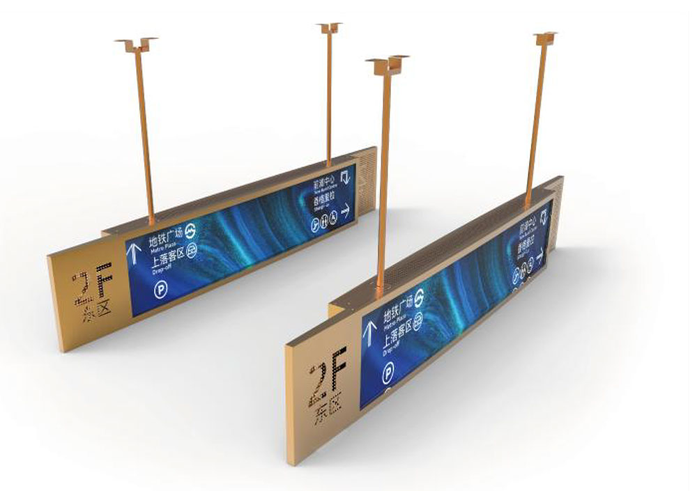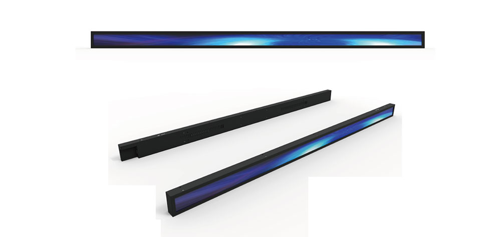
Outdoor and semi-outdoor displays must remain legible under conditions that would wash out a standard monitor. Direct sunlight can reach roughly 100,000 lux, and reflections from the sky, the ground, and nearby surfaces add further light that reaches the viewer's eye. A display designed for an office may measure 300 nits of luminance, which is effectively invisible under midday sun. High-brightness LCDs, typically rated from about 1,000 to 2,500 nits, are engineered to hold image contrast in these conditions. This paper explains the physics behind sunlight readability, the engineering choices that improve it, and the reliability issues that come with higher light output.

## 1. Why Sunlight Degrades Readability
The key metric is not the display's luminance alone but its contrast under ambient illumination. Ambient light falling on the screen reflects off the front surface and the internal layers, adding a light level that is independent of the image content. The effective contrast ratio can be approximated as:
CR_ambient = (L_on + E × R / π) / (L_off + E × R / π)
where L_on is the white-state luminance, L_off is the black-state luminance, E is the illuminance on the screen in lux, and R is the total reflectance of the display surface and internal stack. Because the ambient term is added to both the white and black states, it compresses the ratio. A panel with a native contrast of 1,000:1 in a dark room can drop to near 1.5:1 under full sun if its luminance and reflectance are not controlled.
This relationship defines the design problem. Increasing backlight luminance raises L_on and L_off together, but only the white-state term matters once the ambient term dominates in the denominator. Reducing reflectance is therefore as important as increasing brightness. A good sunlight-readable design addresses both sides of the equation.
## 2. Backlight Engineering
The backlight determines the upper limit of achievable brightness. Most high-brightness LCDs use white LED arrays in either edge-lit or direct-lit configurations. Edge-lit designs are thinner and cost less, but they have limited peak luminance and more difficulty achieving uniformity across large areas. Direct-lit designs place LEDs behind the diffuser, which allows higher total light output and better local control, at the cost of thickness and more complex thermal paths.
Several engineering factors determine how much usable light reaches the viewer:
- LED drive current and count. Higher current increases output but also raises junction temperature, which lowers luminous efficacy and shortens life. Designers typically spread the required light across more LEDs at moderate current rather than driving a few LEDs hard.
- Light guide and reflector efficiency. Reflective films behind the light guide recycle light that would otherwise escape backward. Their reflectivity and the optical pattern on the light guide strongly influence output uniformity.
- Diffuser and prism films. Brightness enhancement films concentrate light toward the normal viewing direction. This raises on-axis luminance, which is useful for a viewer standing in front of the display, but it narrows the viewing cone. Applications with off-axis viewers must balance these effects.
- Local dimming. Mini-LED or zoned backlights can increase perceived contrast by dimming dark regions. In high-ambient environments, local dimming also reduces power draw when displaying mostly dark content, which helps thermal performance.
## 3. Panel Optical Stack
The LCD panel itself transmits only a fraction of backlight output. Each polarizer absorbs roughly half of unpolarized light, and the color filters, TFT array, and liquid crystal layer each reduce transmission further. As a result, a conventional LCD often passes only around 5 to 10 percent of the backlight to the viewer. High-brightness panels address this through several measures:
- High-transmittance polarizers and color filters that reduce absorption without sacrificing color gamut.
- Higher aperture ratio TFT designs, which allow more of the pixel area to transmit light.
- Optimized cell gap and liquid crystal material, chosen to balance response time, transmittance, and viewing angle.
Each of these changes involves trade-offs. Higher transmittance filters can reduce color saturation, and a larger aperture ratio can affect pixel crosstalk. Engineering teams usually set target values for brightness, gamut, and response time together rather than optimizing one parameter in isolation.
## 4. Surface Treatments and Optical Bonding
Reflection from the front surface is one of the largest contributors to ambient degradation. Two main approaches address it:
- Anti-glare (AG) treatments scatter reflected light by texturing the surface. They reduce specular reflection effectively, but they can soften fine text and add haze, which reduces sharpness and contrast in dark-room use.
- Anti-reflective (AR) coatings use thin-film interference to reduce reflectance at specific wavelengths. They preserve image sharpness better than AG, but they are more expensive and can be less durable if not properly protected.
A cover glass or cover lens placed in front of the LCD creates an air gap. Each air-glass interface reflects light, and the gap can also trap moisture and dust and cause internal condensation. Optical bonding eliminates the gap by filling it with a clear adhesive or resin, typically optically clear adhesive (OCA) or optically clear resin (OCR). Bonding reduces internal reflections, improves mechanical rigidity, and lowers the risk of fogging. It also makes the display harder to rework, so the decision should be made early in the mechanical design.
For sunlight-readable products, the common combination is a bonded stack with a well-chosen AR or low-reflectance film and a cover glass with appropriate hardness and impact rating.
## 5. Thermal Management
Brightness and heat are directly linked. Most of the electrical power driving the backlight is converted to heat, and in a sealed outdoor enclosure that heat has limited paths to escape. Elevated temperature affects the display in several ways. LED efficiency declines as junction temperature rises, so the same drive current produces less light. Liquid crystal response and color characteristics shift with temperature. Polarizers and adhesives can degrade faster under sustained heat, causing discoloration or delamination.
Effective thermal design typically includes:
- A metal chassis or heat spreader that conducts heat from the LED boards to the enclosure.
- Thermal interface materials with stable conductivity over the operating temperature range.
- Temperature sensors on the backlight driver or LED board, connected to firmware that reduces brightness when a safe threshold is approached.
- Enclosure design that considers solar loading. Surfaces exposed to direct sun can reach temperatures well above ambient, so the thermal budget must account for radiative heating as well as internal power.
Brightness derating is a standard engineering response. Rather than allowing the display to overheat, controllers reduce drive current when temperature rises. This protects the panel and LEDs, though it means the advertised peak brightness may not be sustained in the hottest conditions. Datasheets should specify whether luminance values are at room temperature or across the full operating range.
## 6. Driver Electronics and Dimming Control
High-brightness displays rely on ambient light sensing to balance visibility and power consumption. An ambient light sensor measures surrounding illuminance, and the controller adjusts backlight output accordingly. This keeps the display readable in bright conditions and avoids excessive brightness indoors, which reduces eye strain and extends LED life.
Dimming method also matters. Pulse-width modulation (PWM) dimming switches LEDs on and off at a controlled duty cycle. It maintains LED color consistency at low brightness but can produce visible flicker if the frequency is too low, and it can interfere with cameras or sensitive viewers. DC dimming reduces current continuously, which avoids flicker but can shift LED color at low levels. Many high-brightness designs use a combination, applying DC dimming over most of the range and PWM at very low levels, with a frequency high enough to avoid visible artifacts.
The driver should also provide protection features, including over-current limits, open and short LED detection, and thermal shutdown. These functions help prevent a single fault from damaging the backlight array.
## 7. Reliability and Lifetime
Higher luminance increases stress on every component in the optical path. LED lifetime is commonly expressed as L70, the time until output falls to 70 percent of initial luminance. Operating at high current and high temperature shortens this figure, so a display rated for 50,000 hours at moderate conditions may achieve a substantially shorter life at maximum brightness in a hot enclosure. Designers should request lifetime data at the actual operating temperature and drive level.
Other reliability concerns include:
- UV exposure. Sunlight contains ultraviolet radiation that can degrade polarizers, adhesives, and color filters. UV-blocking layers and stabilized materials reduce this risk.
- Humidity and condensation. Temperature cycling can draw moisture into the stack. Sealed bonding and appropriate desiccant or venting strategies help prevent fogging.
- Mechanical stress. Outdoor installations face vibration, wind loading, and thermal expansion. Bonding adhesives and mounting structures must accommodate differing expansion rates among glass, metal, and plastic.
- Color and uniformity drift. Over time, LED aging and panel degradation can change white point and luminance uniformity. Calibration routines and compensation tables can help maintain consistency.
## 8. Validation and Testing
Sunlight readability should be validated under conditions that resemble the target environment. Key measurements include:
- Luminance at the panel surface at both room temperature and the maximum operating temperature.
- Ambient contrast ratio measured under controlled illumination levels, with reflectance characterized separately.
- Uniformity across the display area and across the brightness range.
- Viewing angle performance, especially where operators stand at varied positions.
- Environmental testing, including temperature cycling, humidity exposure, UV exposure, and vibration, following applicable test methods such as those in the IEC 60068 series.
- Accelerated life testing at elevated temperature and drive current, with results extrapolated using established models and verified against field data.
Test reports should state measurement conditions clearly. A luminance figure without the temperature, ambient illumination, and drive level has limited value for comparing products.
## 9. Design Checklist
Engineers planning a sunlight-readable LCD can use the following sequence:
1. Define the target ambient illuminance and viewing distance, then calculate the required white-state luminance using the contrast relationship above.
2. Choose a backlight architecture that meets the luminance target with thermal headroom.
3. Select a panel with adequate transmittance and a viewing angle suited to the application.
4. Specify surface treatment and decide between air-gap and optically bonded construction.
5. Design the enclosure and heat paths for worst-case solar loading and maximum internal power.
6. Implement ambient light sensing, temperature-based derating, and protective driver functions.
7. Qualify the design against UV, humidity, temperature cycling, and lifetime requirements.
8. Document all measurement conditions in datasheets and validation reports.
## Conclusion
High-brightness LCD performance in sunlight depends on a system of linked decisions rather than a single specification. Peak luminance matters, but ambient reflectance, optical bonding, thermal design, dimming strategy, and long-term reliability determine whether the display remains readable and durable in the field. Engineers who evaluate these factors together, and who verify performance under realistic temperature and illumination conditions, are better positioned to deliver displays that perform reliably where sunlight is strongest.
KEYWORDS: high-brightness LCD, sunlight-readable display, outdoor LCD, LED backlight, optical bonding