1. Why Outdoor Readability Is a Different Engineering Problem
Indoor LCDs are designed around a comfortable viewing environment, typically 200 to 400 lux of ambient light. Outdoor displays must operate in conditions that can exceed 100,000 lux under direct sunlight. At that level, the display competes with the sun as a light source, and the displayed image is only useful if its luminance remains clearly above the light reflected from the screen surface.
This is the central problem of sunlight-readable LCD design. The panel must emit enough light to overpower reflected ambient light, and its internal optical structure must minimize the amount of ambient light that reflects back toward the viewer. Brightness alone is not sufficient. A high-luminance panel with a poorly controlled optical stack can still produce a washed-out image, while a well-engineered stack with moderate luminance can outperform it.
2. Understanding Ambient Reflection and Contrast
The luminance contributed by ambient reflection can be approximated as:
L_ambient = (R × E) / π
where R is the effective reflectance of the display surface and internal layers, and E is the illuminance incident on the display in lux. The result is in cd/m² (nits).
Contrast under ambient light is then approximated by:
CR = (L_on + L_ambient) / (L_off + L_ambient)
where L_on is the luminance of a white pixel, and L_off is the luminance of a black pixel. Both L_on and L_off include the ambient term, which is why ambient light compresses contrast so severely.
Consider a display with an effective reflectance of 3 percent under 100,000 lux. The ambient term is approximately 0.03 × 100,000 / π, or about 950 nits. Even if the panel's black state is near zero, the black level under sunlight rises to roughly 950 nits. To achieve a usable contrast ratio of 3:1 under these conditions, the white state must reach approximately 2,850 nits. This simple calculation explains why sunlight-readable designs target luminance in the thousands of nits, and why reducing reflectance is just as important as increasing backlight output.

3. Target Luminance Levels by Use Case
Requirements vary significantly with the deployment environment. The following ranges are representative of common engineering targets:
Shaded outdoor or covered kiosks: approximately 1,000 to 1,500 nits.
Semi-exposed environments such as transit shelters and fuel station canopies: approximately 1,500 to 2,500 nits.
Direct sunlight exposure, such as vehicle-mounted and open-air field displays: approximately 2,500 to 5,000 nits or higher.
Designers should specify the maximum expected ambient illuminance and the minimum acceptable contrast ratio, then derive the required luminance rather than selecting a panel by its brightness rating alone. Brightness ratings are typically measured at the center of the panel in a dark room, and they do not account for reflectance or uniformity in service.
4. Backlight Architecture and Light Efficiency
The backlight is the primary source of luminance, and its design determines both peak brightness and power consumption. High-brightness backlights typically use arrays of white LEDs coupled to a light guide plate or a direct-lit diffuser. Key design factors include:
LED selection and count. Higher drive currents increase luminous output but also increase junction temperature. Designers must balance the number of LEDs against the required uniformity, heat spreading, and driver capacity.
Light guide and diffuser geometry. Edge-lit designs achieve slim profiles but face limits in maximum luminance and thermal dissipation. Direct-lit designs allow higher peak output and better local dimming control, at the cost of thickness and cost.
Reflector efficiency. The reflective sheet behind the light guide recycles light that would otherwise escape. High-reflectivity films improve system efficiency, but their performance degrades with heat and UV exposure, so long-term material stability must be verified.
Prism and brightness enhancement films. Prism films concentrate light toward the normal axis, increasing on-axis luminance. They also narrow the viewing cone, which can be advantageous for outdoor use where viewers are typically in front of the display, but may reduce off-axis visibility.
An LCD is inherently inefficient. Polarizers, color filters, and the liquid crystal layer together transmit only a small fraction of the backlight output, typically in the range of 5 to 8 percent of the emitted light reaching the viewer. This means that every optical loss in the stack has a direct cost in required LED power and heat.
5. Reducing Surface and Internal Reflectance
Reflectance control is the second lever for sunlight readability, and it is often more cost-effective than increasing backlight power.
Each air-to-glass interface reflects roughly 4 percent of incident light at normal incidence. A stack with several uncoated air gaps can therefore reflect a substantial fraction of ambient light before it reaches the polarizer. Optical bonding, which fills the gap between the cover glass or touch sensor and the LCD module with a transparent adhesive or resin, eliminates several of these air interfaces. The result is lower surface reflectance, improved contrast, and reduced internal glare.
Surface treatments fall into two broad categories:
Anti-glare (AG) treatments diffuse reflected light and reduce specular reflections. They are effective at softening reflections but can reduce image sharpness and slightly lower perceived contrast in low ambient conditions.
Anti-reflection (AR) coatings use thin-film interference to reduce the reflectance of each surface. Multilayer AR coatings can reduce reflectance to well below 1 percent per surface, but they add cost and must be durable enough for outdoor handling and cleaning.
Many outdoor products combine optical bonding with AR coatings on the outermost surface. The specific combination should be selected based on the expected reflection environment, the required image sharpness, and the surface durability requirements.
Polarizer selection also matters. High-transmittance polarizers improve the efficiency of the backlight, but polarizers with very high transmittance may reduce contrast if their extinction ratio is insufficient. Engineers should evaluate both transmittance and extinction ratio together.
6. Thermal Management and Long-Term Reliability
High luminance creates heat, and heat affects nearly every subsystem of the display. LED efficiency decreases as junction temperature rises, and LED lumen maintenance declines faster at elevated temperature. Liquid crystal response, polarizer stability, and adhesive performance are also temperature-dependent.
Effective thermal design typically includes:
A metal chassis or heat spreader in direct contact with the LED board, with thermal interface materials selected for long-term stability.
Thermal modeling of the full stack at maximum ambient temperature and maximum drive current, including solar heat load on the enclosure. Direct sunlight can raise the surface temperature of an enclosure well above the air temperature, so the thermal analysis must include solar radiation, not only ambient air temperature.
Temperature-based brightness control. Many high-brightness designs include temperature sensors that reduce LED current when internal temperature exceeds a set threshold. This protects the LEDs but means that peak brightness may not be available continuously in hot conditions. Specifications should state whether brightness is rated at a defined temperature.
Lifetime projection based on L70 or similar lumen maintenance metrics measured at the operating temperature, not at room temperature. Lifetime claims that do not specify temperature conditions should be treated with caution.
7. Measurement and Validation
Sunlight readability cannot be verified by brightness measurement alone. A complete validation program should include the following measurements.
Luminance and uniformity. Measure luminance at multiple points across the active area, commonly nine or thirteen points, under defined drive conditions. Report both the maximum luminance and the uniformity ratio, which is the ratio of minimum to maximum luminance. Low uniformity produces visible hot spots and dark regions in outdoor use.
Reflectance. Measure the specular and diffuse reflectance of the complete display surface using a calibrated goniometric setup. Reflectance should be reported with the measurement geometry specified, because values differ with incidence angle.
Ambient contrast ratio. Simulate ambient illumination using a controlled light source at known illuminance, and measure the contrast ratio at the required viewing angle. This test captures the combined effect of luminance, reflectance, and optical stack design, and it is the most meaningful single indicator of outdoor performance.
Viewing angle and color shift. Because outdoor viewers are often positioned off-axis, measure luminance and color coordinates at multiple angles. Excessive color shift at moderate angles can make content difficult to interpret even when the on-axis image appears bright.
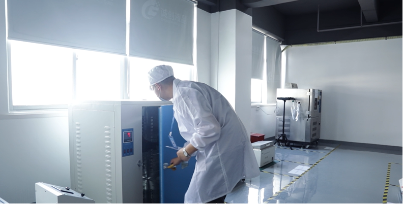
Environmental testing. Subject the display to temperature cycling, high-temperature operation, humidity exposure, and UV exposure. Optical bonding adhesives, AR coatings, and polarizers should be checked for yellowing, delamination, and changes in transmittance after exposure.
8. Design Trade-Offs
Sunlight-readable design is a balance among competing requirements. Increasing luminance raises power consumption, heat load, and cost. Adding AR coatings and optical bonding improves contrast but increases manufacturing complexity. Stronger prism films increase on-axis brightness but reduce viewing angle. Each decision should be evaluated against the target environment rather than optimized in isolation.
A practical approach is to start from the required ambient contrast ratio and the maximum expected illuminance, derive the required luminance, then work backward through reflectance reduction, optical efficiency, thermal capacity, and lifetime targets. This method ensures that the final design meets the actual viewing conditions rather than a headline brightness figure.
9. Conclusion
High-brightness LCDs for outdoor use are defined by their ability to remain readable under strong ambient light, not by peak luminance alone. Ambient reflection sets the minimum luminance a display must reach, while optical stack design determines how much of that luminance is effective. Backlight efficiency, reflectance control, thermal management, and rigorous ambient-contrast testing together determine whether a display performs reliably in sunlight. Engineers who evaluate these factors as a connected system will produce displays that remain legible where it matters most.
KEYWORDS: sunlight-readable LCD, high-brightness LCD, outdoor LCD display, ambient contrast ratio, nits brightness