Introduction to High-Brightness LCD Engineering
Outdoor
displays must remain legible under direct sunlight, where ambient illumination can exceed 100,000 lux. A standard indoor LCD with roughly 250 to 350 nits of luminance becomes nearly unreadable in these conditions. High-brightness LCD design addresses this problem through a coordinated approach that spans the backlight, the optical stack, the thermal path, and the validation process. This article explains the engineering principles behind sunlight-readable LCDs and outlines the design decisions that determine real-world performance.
Why Sunlight Washes Out Standard Displays
The Contrast Problem

Sunlight reaches the
display surface and reflects back toward the viewer. The reflected luminance can be estimated with a simple relationship:
L_reflected ≈ (R × E) / π
where R is the effective surface reflectance and E is the illuminance at the screen. For a
display with 5 percent effective reflectance under 100,000 lux, the reflected luminance is about 1,600 cd/m². If the panel emits only 350 nits, the contrast ratio collapses toward 1:1 because the reflected light dominates the image. This is why the core goal of high-brightness design is to raise emitted luminance and simultaneously reduce unwanted reflection.
Brightness Targets by Environment
Brightness requirements depend on the usage environment. Indoor and office use typically needs 300 to 500 nits. Shaded outdoor areas, such as covered kiosks, generally call for 1,000 to 1,500 nits. Partially sunlit or semi-outdoor installations often require 1,500 to 2,500 nits, while direct-sun applications such as marine, automotive, and open-air signage commonly target 2,500 nits or more. Specifying a target without defining the ambient illuminance and reflectance conditions leads to inaccurate designs, so these parameters should be documented from the start.
Backlight Architecture
LED Count, Placement, and Light Guiding
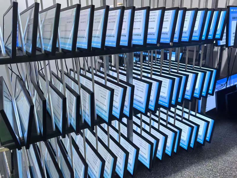
The backlight is the dominant factor in achieving high luminance. Direct-lit architectures place LEDs behind the panel and generally deliver higher peak brightness and better local dimming potential. Edge-lit designs use a light guide plate and allow thinner enclosures, but they face efficiency limits as panel size grows. High-brightness products usually favor direct-lit or dense edge-lit arrays with optimized reflector sheets and high-efficiency diffusers.
Efficiency and Light Recycling
Much of the light generated by the backlight never reaches the viewer. Reflective films, prism sheets, and diffuser optimization recover light that would otherwise be lost inside the cavity. Each additional film adds some absorption, so the stack must balance uniformity against optical efficiency. Engineers should measure luminance uniformity at the panel level, not only at the LED level, because local hotspots and dark zones are common failure modes in high-output backlights.
Panel Transmittance and Polarizer Selection
Light Loss Through the Panel
A conventional TFT LCD transmits only a fraction of its backlight. Two polarizers, color filters, and the TFT aperture each absorb or block light. Typical standard polarizers transmit around 40 to 44 percent of unpolarized light, and the overall panel transmittance is often in the single-digit percentage range.
High-brightness panels use high-transmittance polarizers, improved aperture ratios, and optimized color filter materials to increase the fraction of backlight that reaches the viewer.
Trade-Offs in Panel Optics
Raising transmittance often reduces contrast or narrows viewing angles, so the panel and backlight must be designed together. A higher-output backlight can compensate for a lower-transmittance panel, but at the cost of power consumption and heat. The optimal combination depends on the target contrast ratio, viewing angle, and thermal budget of the final product.
Optical Bonding and Reflection Control
Why Air Gaps Hurt Readability
Each air-to-glass interface reflects roughly 4 percent of incident light at normal incidence. A cover glass with an air gap above the LCD creates multiple reflective surfaces, and these reflections add directly to the ambient light problem. Optical bonding fills the gap with a transparent adhesive, such as optically clear adhesive or optically clear resin, which removes the air interfaces and reduces internal reflections. Bonding also improves mechanical durability and reduces condensation risk.
Surface Treatments
Anti-reflection coatings lower the reflectance of the outer surface, while anti-glare treatments scatter reflected light. Anti-reflection films are generally more effective for reducing specular reflection in high-contrast environments, but they can be costlier and more sensitive to handling. Anti-glare treatments reduce mirror-like reflections but can soften image sharpness and increase haze. The choice depends on whether the application prioritizes clarity, glare suppression, or touch performance.
Thermal Management
Heat as a Luminance Limit
LED efficiency decreases as junction temperature rises, and luminance output drops accordingly. A display that reaches its target brightness at 25 °C may fall short at 60 °C inside a sealed enclosure in direct sun. Thermal design therefore determines whether the rated brightness is available in the field, not only in the laboratory.
Practical Heat Paths
Effective thermal design routes heat from the LED arrays to the chassis and then to the ambient environment. Key measures include:
- Thermally conductive mounting between the LED boards and the metal chassis
- Adequate heat-sink area sized for the worst-case ambient temperature
- Sealed enclosures designed to avoid trapping heat without compromising ingress protection
- Thermal sensors that feed back into the driver for brightness derating
Driver Electronics and Dimming Control
Brightness Control Methods
High-brightness displays rely on precise dimming control. Pulse-width modulation (PWM) dimming controls the backlight by switching the LEDs on and off, but low PWM frequencies can produce visible flicker and may affect camera imaging. Constant-current dimming adjusts LED current directly and avoids flicker, though it can shift color at low brightness levels. Many designs combine both methods, using current control at higher levels and PWM at lower levels.
Ambient Light Adaptation
An ambient light sensor allows the display to adjust brightness automatically as lighting conditions change. This prevents the display from running at full power in dark environments and conserves energy. The control curve should be tuned to human perception, and the sensor should be placed to avoid being shadowed or saturated by the display's own output.
Validation and Reliability Testing
Key Measurements
Validation should confirm the performance metrics that matter in the field. Important tests include:
- Luminance and uniformity measured at multiple points across the active area
- Contrast ratio measured under simulated ambient illuminance
- Color accuracy and white-point stability across the brightness range
- Viewing-angle performance after bonding and surface treatment
- Thermal soak tests at maximum rated ambient temperature
- Temperature cycling and humidity exposure to verify bonding integrity
Lifetime and Brightness Decay
LED backlight lifetime is commonly specified as the time until luminance falls to 70 percent of its initial value, often written as L70. High-brightness products operating at high drive currents may age faster, so lifetime specifications should be verified at the actual operating temperature and drive level rather than only at nominal conditions.
Design Checklist for Sunlight-Readable LCDs
Before finalizing a high-brightness design, engineers should confirm the following:
- Target luminance is defined for the specific ambient illuminance and reflectance conditions
- The backlight delivers the required luminance after panel and optical losses
- Optical bonding and surface treatments are selected to minimize reflection
- Thermal design sustains rated brightness at maximum ambient temperature
- Dimming and ambient light control are tuned for both comfort and efficiency
- Validation covers luminance, contrast under ambient light, thermal behavior, and lifetime
Sunlight readability is a system-level property. Achieving it requires balancing backlight output, panel transmittance, optical bonding, surface treatment, and thermal performance together. Designs that optimize one element in isolation often fail when deployed outdoors, while integrated design delivers displays that remain clear, accurate, and reliable in the most demanding lighting conditions.
KEYWORDS: high-brightness LCD, sunlight-readable display, LCD backlight luminance, optical bonding, outdoor LCD display