A display's operating temperature range defines the conditions under which it can produce a stable, readable image without permanent damage. For high-brightness LCDs deployed outdoors, in vehicles, in industrial control cabinets, and in transportation systems, a rating of -20°C to +70°C is a practical requirement. This article explains what that rating means, which physical mechanisms limit it, and how it is achieved and verified in a well-engineered high-brightness LCD.
Operating range is not the same as storage range. Storage specifications usually cover a wider span because the panel is unpowered and no electrical or optical performance is required. An operating range applies while the display is powered, driven with video, and expected to meet its specified brightness, contrast, response time, and color performance. Engineers should therefore read the operating limit as the envelope within which every specified parameter holds, not merely the envelope within which the glass survives.
The liquid crystal layer sets the first boundary. Liquid crystal molecules change orientation under an applied electric field, and the speed of that reorientation depends strongly on viscosity. As temperature falls, viscosity rises and the response time lengthens. At -20°C a standard commercial panel may show visible smearing, slow grayscale transitions, and uneven gamma. Industrial formulations use low-viscosity liquid crystal mixtures and optimized cell gaps to keep response times within limits at the low end of the range. Cell gap is adjusted with the cell's birefringence in mind, so that transmittance and contrast remain balanced across temperature. At the high end, the concern shifts. Liquid crystal materials have a clearing point, the temperature at which they lose their ordered phase, which lies well above 70°C in qualified materials. Operating at +70°C therefore keeps the liquid crystal far from its clearing point, preserving alignment stability and preventing image retention caused by thermal stress.
Polarizers and other optical films form the second boundary. Polarizing films are organic composites, and prolonged exposure to high temperature accelerates shrinkage, stress relaxation, and degradation of the iodine-based polarizing element. Retardation films and compensation layers have similar limits. Selecting films rated for elevated temperature, and specifying adhesives that do not creep or delaminate under thermal cycling, is essential. When a panel is qualified to +70°C, the polarizer stack is verified at that temperature for the full rated service life, not just briefly.
The backlight is usually the most demanding element in a high-brightness LCD. White LEDs convert electrical energy into light with an efficiency that declines as junction temperature rises. Higher junction temperature also reduces the long-term lumen maintenance of the LED package and can shift its correlated color temperature. At an ambient of +70°C, the LED junction runs even hotter, so the thermal path from die to chassis must be designed with care. This includes low-resistance die attach, metal-core or ceramic LED substrates, thermally conductive adhesives, and a heat-spreading aluminum chassis that transfers heat to the enclosure or a heat sink. Driver circuits must also be derated at high temperature, and the backlight current must be managed so that luminance remains within specification without overstressing the LEDs.
High brightness creates a further thermal challenge. A display that reaches 1500 nits or more dissipates considerable power, and much of that power becomes heat inside the module. Even at a moderate ambient temperature, the internal temperature of the panel and backlight can exceed the outside air by a significant margin. For this reason, the operating limit must be understood as an ambient or case temperature specification, with the thermal design ensuring that internal components remain within their own limits. Some designs use automatic brightness reduction when internal temperature sensors approach a threshold. This thermal derating protects the LEDs and polarizers while keeping the display functional, although the luminance is reduced in the hottest conditions.
The low end of the range introduces start-up and condensation issues. At -20°C, a cold display may take longer to reach full brightness, and the liquid crystal may show temporary slow response until the panel warms through self-heating. Some industrial designs include a heater film or a controlled warm-up sequence that brings the panel to a minimum temperature before full drive begins. This prevents unstable images, flicker, or damage from driving a frozen-slow cell at full speed. Heaters must be controlled by a temperature sensor placed near the panel, and their power budget must be included in the system design.
Condensation is another risk, particularly when a display moves between cold and warm environments. When a cold panel is exposed to humid air, moisture can condense on the glass or inside the module if the enclosure is not sealed. Internal condensation can cause fogging, electrical leakage, and corrosion. Proper design addresses this through a hermetically sealed or gasketed enclosure, a desiccant or breathable membrane that equalizes pressure without admitting moisture, and conformal coating on driver boards. Gradual warm-up and controlled thermal transitions reduce the rate of temperature change that drives condensation.
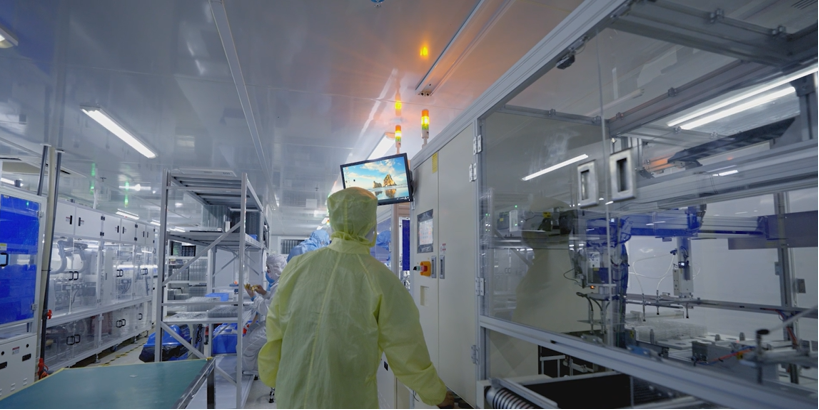
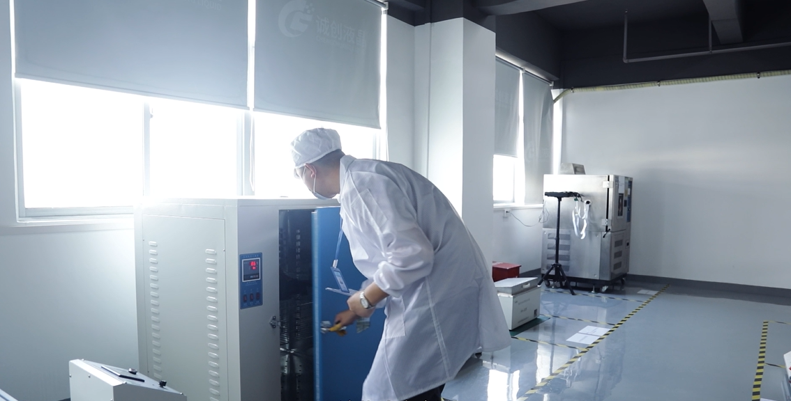
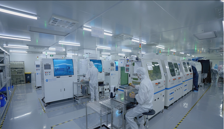
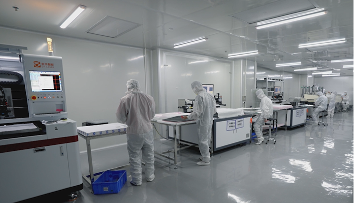
Verification is what transforms a design target into a rated specification. Cold operation is typically tested according to IEC 60068-2-1, which covers low-temperature exposure with the device powered and monitored. Dry heat operation follows IEC 60068-2-2. Temperature change tests, described in IEC 60068-2-14, expose the display to repeated transitions between the limits to reveal solder joint fatigue, adhesive failure, and film delamination. For vehicle and military applications, MIL-STD-810 methods may also apply. During testing, engineers measure luminance, contrast, response time, color coordinates, and image quality at the low limit, at room temperature, and at the high limit. A qualified unit must meet the specified performance at both extremes, not just survive them without power.
Finally, the -20°C to +70°C rating should be treated as a system-level commitment. The panel, backlight, driver electronics, enclosure, adhesives, and sealing all contribute to whether the display can operate across the full range. Selecting a display with a verified wide operating temperature range, and confirming that its test reports cover the specific brightness level and operating mode needed, gives system designers confidence that the image will remain stable from a winter dawn to a summer afternoon in direct sunlight.
KEYWORDS: high-brightness LCD, operating temperature range, -20°C to +70°C, industrial LCD display, wide temperature LCD