Why the Display Is a System Component, Not an Accessory
In EV charging posts and fuel dispensers, the display is the only surface a customer physically interacts with during a transaction. It carries legally relevant data — unit price, volume dispensed, kWh delivered, total amount due — and it must remain legible across a temperature range that would shut down a consumer tablet, under direct sun at 100,000 lux, behind a sealed window that may sit ten metres from the controller cabinet. Engineers who treat the LCD as a catalogue item to be picked at the end of the project almost always pay for it later, in re-spins, field failures, or metering re-certification.
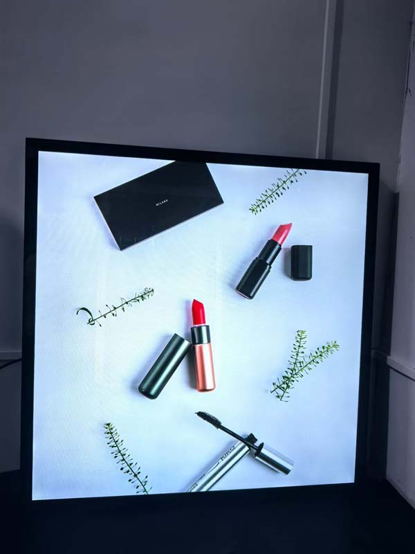
This guide walks through the integration decisions that actually determine whether a display survives ten years at a roadside site: optical stack-up, backlight thermal design, interface signal integrity, sealing, EMC, and the regulatory obligations that differ between a fuel dispenser and an EV charger.
1. Define the Environmental Envelope First
Before selecting glass, write down the operating envelope. Everything downstream — brightness, heater power, gasket compression, adhesive chemistry — is derived from it. A typical dual-use outdoor HMI specification looks like this:
| Parameter | Fuel dispenser | EV charging post (AC / DC) |
|---|---|---|
| Operating temperature | −40 °C to +70 °C (electronics bay often +55 °C ambient with solar gain) | −30 °C to +55 °C; DC fast chargers add internal heat load from the power stage |
| Storage temperature | −40 °C to +85 °C | −40 °C to +80 °C |
| Ambient illumination | Up to 100,000 lux, plus specular flare from low sun | Same, with additional reflection from the vehicle body |
| Ingress protection | Front face IP54 minimum; IP65 common on the display window | IP54 (IEC 61851-1) to IP65 for outdoor kerbside units |
| Impact | IK08 for nozzle/hose contact; IK10 on vandal-prone kerbside glass | IK10 recommended; touch surface must survive coin and key strikes |
| Chemical exposure | Petrol, diesel, E10/E85 ethanol blend, AdBlue (urea), screen wash, oil | AdBlue, brake fluid splash, de-icing salt, alkaline car-wash detergent |
| Hazardous area | Zone 1 or Zone 2 per IEC 60079-10-1; display assembly may need Ex e or Ex d segregation | Normally non-hazardous; battery room installations may require Zone 2 assessment |
Two entries deserve emphasis. First, solar gain: a dark grey enclosure in direct summer sun can push the internal air 20–25 °C above ambient, so an "ambient" spec of 55 °C is really a 75–80 °C component requirement. Second, the hazardous-area classification on fuel dispensers constrains the display's power budget and wiring routing — an Ex-rated backlight driver and current-limited interface are often mandatory, and any non-compliant modification invalidates the dispenser's certification.
2. Regulatory Obligations That Touch the Display
Legal metrology. Displayed transaction data is part of the measuring instrument. Under the EU Measuring Instruments Directive (2014/32/EU), fuel dispensers are covered by Annex MI-005 and EV charging stations by Annex MI-003 (active electrical energy meters). OIML R 117 (fuel) and OIML R 46 (electricity) define the presentation requirements: digits must be unambiguous, character height must be sufficient for reading at the intended distance (as a working rule, digit height in millimetres ≈ viewing distance in metres × 3 to 5 for comfortable reading), the unit symbol must be shown, and the display must remain readable when the backlight has failed. This last clause is decisive — it rules out transmissive-only TFTs as the sole indication of price and volume unless a transflective layer or a separate segment LCD is added.
Evaluation and certification tracks. Fuel dispensers typically follow UL 87 / EN 13617 with ATEX or IECEx for the hazardous zone; EV supply equipment follows IEC 61851-1, UL 2594 or UL 2202 for DC, plus IEC 62196 for the connector. Neither standard specifies the display, but all of them impose EMC, insulation and fault-condition requirements on it indirectly.
Payment. If a card reader is integrated, PCI PTS covers the terminal but not the HMI. However, the display must not be able to render counterfeit prompts, and the PIN-entry flow must be visually distinct from advertising content — a design constraint on firmware and on hardware layering (secure overlay vs. general UI).
3. Choosing the Display Technology
| Technology | Best fit | Trade-offs |
|---|---|---|
| Static segment TN/FSTN LCD | Price, volume, total on fuel dispensers | Sunlight-legible with transflective polariser and zero backlight power; no graphics, fixed layout |
| Monochrome graphic COG/FSTN | Simple instruction prompts, low-cost AC posts | Limited animation, narrow temperature compensation window |
| Transmissive TFT, TN mode | Indoor or shaded canopies | Poor off-axis contrast; unusable in direct sun without very high brightness |
| IPS / FFS TFT with high-brightness backlight | Mainstream EV charger UI, payment flow, advertising | Needs 1,000–1,500 cd/m² plus anti-reflective bonding; thermal load on backlight |
| Transflective IPS TFT | Dual-mode: bright sun and power-saving night | Lower peak colour saturation, higher unit cost, thicker stack |
A frequent and expensive mistake is choosing a 1,000 cd/m² transmissive panel and assuming it is "sunlight readable". It is not, unless the reflection path is also controlled. Brightness alone does not create contrast in a bright environment.

4. The Optical Stack: Where Sunlight Readability Is Actually Won
Perceived contrast ratio in an illuminated environment follows, approximately:
CR = (L_white + L_reflected) / (L_black + L_reflected)
At 100,000 lux with a diffuse white surface, luminance is around 30,000 cd/m². A 1% effective reflectance therefore contributes roughly 300 cd/m² of stray light — comparable to the panel's own white output. Raising brightness from 800 to 1,200 cd/m² buys far less than cutting reflectance from 6% to 1%.
Reflection budget
- Each uncoated air–glass interface reflects ~4%. A conventional bonded-free module with a separate window has four such interfaces (cover glass front and back, LCD front polariser, LCD rear), i.e. ~16% total.
- Optical bonding with an index-matched adhesive (n ≈ 1.48–1.52) eliminates two interfaces and the internal window of air, typically taking total reflectance to 2–3%.
- An anti-reflective (AR) coating on the outer face, with multi-layer broadband design giving <0.5% average reflectance in the 450–650 nm band, plus an anti-glare (AG) treatment of 60–90 gloss units to break up specular flare, brings the system to ~1%.
Practical bonding decisions
Silicone gel bonding tolerates thermal expansion and is repairable, but it is softer, harder to keep within the window frame, and can show edge bubbles after 500 thermal cycles. UV-cured liquid optically clear adhesive (LOCA) gives better optical quality and mechanical rigidity, and is the usual choice for a rigid cover glass, provided the cure schedule is validated at the maximum thickness and the adhesive's CTE mismatch to the cover glass and polariser is modelled. For polycarbonate windows — common on vandal-resistant kerbside units — bonding is more difficult because PC outgasses and deforms; a pressure-sensitive optically clear adhesive on a rigid inner carrier is often the safer route.
Finally, verify the AR coating against abrasion and chemical attack. A coating optimised for laboratory reflectance may fail a 500-cycle steel-wool test or degrade after repeated AdBlue contact.
5. Backlight Design and Thermal Reality
High brightness is a thermal problem disguised as an optical one. An edge-lit 10.1-inch panel at 1,200 cd/m² may dissipate 8–12 W in the LED bar, concentrated along one or two edges. Recommendations:

- Derate LED forward current using the manufacturer's lumen-maintenance curves at the actual local board temperature, not the enclosure ambient. L70 at 60 °C junction can be half the life at 40 °C.
- Mount the LED bar against an aluminium chassis with a thermally conductive interface pad, and route heat away from the liquid crystal itself — polarisers yellow and lose transmission above ~85 °C.
- Use constant-current drivers with open/short detection, and report LED faults to the controller over I²C or a diagnostic pin. A dark display on a fuel dispenser is a safety and revenue event, not a cosmetic one.
- Dimming: PWM below 200 Hz is visible as flicker and interacts badly with phone cameras used for QR payment and with surveillance systems, producing rolling bands. Use ≥2 kHz PWM with a filtered driver, or hybrid analogue-plus-PWM dimming, and characterise flicker at 10%, 50% and 90% duty.
- Implement ambient-light-based auto-dimming with hysteresis and a night-time floor (typically 80–150 cd/m²) so the unit does not glare into a driver's eyes at 03:00.
6. Cold-Start Behaviour and Heating
Directive-mode liquid crystals respond slowly below −20 °C; at −30 °C a TN panel can take several seconds to reach workable contrast, and the backlight driver's electrolytic capacitors may not start at all. Two defensive measures:
- Transparent ITO or wire heater bonded to the rear polariser or to the cover glass. Budget 0.5–1.5 W per square decimetre to raise the panel 10–15 °C above ambient in still air, and design the control loop so the heater runs before the backlight ignites. Use a thermistor on the LCD glass, not on the PCB.
- Cold-capable driver components. Specify polymer or ceramic capacitors rated to −40 °C, and validate power-up at −30 °C after a 24-hour soak with the unit unpowered.
Condensation is the companion problem. A sealed enclosure with no pressure equalisation will draw moisture in as internal air contracts at night. Fit a breathable ePTFE vent in the lower part of the housing and, on large windows, an anti-fog coating on the inner surface.
7. Interface, Signal Integrity and EMC
Display signals are the fastest digital nets in the unit and the most likely to leak. Practical guidance:
- Interface choice by distance. RGB parallel is limited to roughly 100 mm of FFC; LVDS is reliable to about 200–300 mm unshielded and 1 m with shielded twisted pair; MIPI DSI should stay inside the module assembly; eDP is appropriate when the controller sits in a separate cabinet several metres away and runs in differential pairs through a sealed conduit.
- Clock spread spectrum on the LVDS/eDP source reduces radiated emissions at the panel-link frequency, which commonly sits inside the 30–230 MHz band that CISPR 32 / EN 55032 measures. Validate that the panel's receiver tolerates 0.5–1% down-spread.
- Return-path discipline. The FFC shield must be bonded to chassis at both ends with a 360° clamp, not a pigtail. Differential pairs must not cross a plane split.
- Immunity. EV chargers must survive the switching noise of a 30–350 kW power stage on the same enclosure, plus contactor chatter and surge. Expect to test to IEC 61000-6-2 and to run radiated immunity at 10 V/m across 80 MHz–6 GHz, with particular attention below 1 GHz where long FFCs act as antennas. A display that resets or shows tearing during a charging session is usually a ground-bounce problem on the interface, not a firmware bug.
- ESD. Touch panels must pass ±15 kV air and ±8 kV contact on the front surface. This constrains the air gap behind the cover glass and demands a dedicated ESD return path from the touch controller to chassis.
8. Touch Integration
Projected capacitive touch is now standard on EV chargers and increasingly common on fuel dispensers. Key integration points:
- Thick cover glass changes the design. At 4 mm, sensor pitch and ITO bridge width must be increased; at 6 mm (IK10 requirement), aluminium or copper mesh sensors may be needed to maintain SNR.
- Wet and gloved operation. Tune the controller for self-capacitance mutual-scan rejection, enable water-film rejection, and validate with a 2 mm nitrile glove and with a 3 mm water film. If the UI is used in winter rain, glove support is a functional requirement, not a nice-to-have.
- Noise. The touch controller must be synchronised to the display's vertical blanking interval, or at minimum to the backlight PWM, to avoid false touches modulated by the LED driver.
- Accessibility. Touch targets of at least 15 mm, tactile feedback through a piezo buzzer, and a mechanical or audio alternative for any critical function, since a touch failure must not prevent an emergency stop.
9. Mechanical Sealing and Chemical Resistance
Front-face sealing is usually achieved with a moulded EPDM or silicone gasket compressed 25–35%, with a continuous bead and no sharp corners under 3 mm radius. Do not rely on adhesive gaskets alone for IP65; specify a mechanical clamp ring. For hazardous-area fuel dispensers, the display window may need to be part of an Ex e enclosure — meaning flameproof or increased-safety sealing, defined cable entries, and no user-accessible fasteners.
Material compatibility matters more than most teams expect. Polycarbonate crazes with prolonged petrol contact; chemically strengthened glass is immune to fuels but fails the impact-versus-mass trade-off differently. Specify a hard coat of at least 3H pencil hardness and test 24-hour immersion or wipe-down with the actual fluids on site.
10. Firmware and UI Considerations
- Boot time. The customer expects a prompt within two seconds of KEYWORDS: LCD Display Integration Guide for EV Charging and Fuel Dispensing Equipment