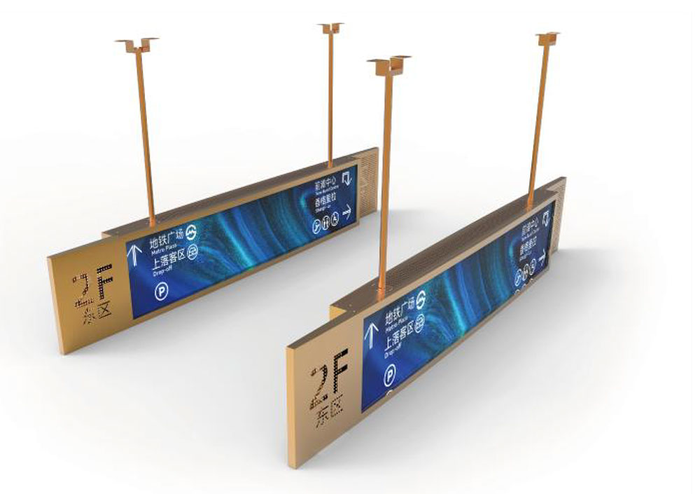
Outdoor displays must remain legible under direct sunlight, where ambient illuminance can exceed 100,000 lux. Under those conditions, a standard indoor LCD with 250 to 350 nits of luminance loses nearly all of its visible contrast. Sunlight-readable designs usually target 1,000 to 2,500 nits, depending on the application, viewing angle requirements, and how much reflected light the front stack must overcome. This article explains the physics behind that target, the optical and thermal trade-offs involved, and the engineering decisions that determine whether a high-brightness LCD performs as specified in the field.
Why ambient light is the real problem
A display's readability depends on contrast under ambient illumination, not on its luminance in a dark room. Light from the sun or sky reflects off the cover glass, the polarizer, and the internal layers of the panel, and that reflected light adds to the light the display emits. Reflected luminance can be estimated as L_r = R × E / π, where R is the surface reflectance and E is the illuminance on the screen.
Consider a panel with a 4 percent surface reflectance exposed to 100,000 lux. The reflected luminance is roughly 1,270 cd/m². If the display emits 1,500 nits in its on state and 1 nit in its off state, the effective contrast ratio falls to about (1,500 + 1,270) / (1 + 1,270), or roughly 2.2:1. That is well below the 3:1 to 4:1 commonly cited as a minimum for comfortable reading. Reducing reflectance to 1 percent with a quality anti-reflection coating lowers the reflected term to about 320 nits and raises the contrast to roughly 5.6:1. The lesson is that brightness and reflection control must be designed together. Raising luminance alone has diminishing returns if the front stack returns a large fraction of ambient light to the viewer.
Where the light goes: the transmission chain
A conventional transmissive LCD is an inefficient optical system. The backlight passes through a rear polarizer, which transmits roughly 40 to 45 percent of unpolarized light. The liquid crystal layer and TFT array then modulate the light, with the aperture ratio and layer losses reducing transmission further. The color filter absorbs most of the light outside each subpixel's passband, typically transmitting only about a quarter to a third of the remainder. The front polarizer then passes roughly 40 percent of what remains.
The combined result is an overall optical transmission of about 3 to 6 percent from backlight to viewer. This arithmetic explains why high-brightness designs require very bright backlights. To produce 1,500 nits at the viewing surface with 5 percent transmission, the backlight must deliver an equivalent of roughly 30,000 nits at the panel's input side, before accounting for optical losses in diffusers and light guides. Engineers therefore evaluate backlight units, panel transmission, and driver capability as one system rather than as independent components.
Backlight architecture
Edge-lit designs with a light guide plate can achieve high uniformity in thin packages, but they are limited by the number of LEDs that can couple into the guide and by heat accumulation along the edges. Direct-lit designs place LEDs behind the panel and can reach higher peak luminance with better thermal distribution, at the cost of thickness and the need for careful diffuser design to hide LED hotspots.
Diffuser and prism film stacks should be selected to recycle light efficiently. Brightness-enhancing films increase on-axis luminance by directing off-axis light toward the viewer, but they narrow the viewing cone. For outdoor kiosks and vehicle displays where viewers stand or sit in predictable positions, this trade-off is often acceptable. For handheld devices viewed from many angles, a wider cone may be more important than peak on-axis brightness.
Local dimming and zone control can improve contrast in high-brightness products, but they introduce halo artifacts near bright features and require accurate zone mapping and driver synchronization. These designs are best justified when the content includes high dynamic range imagery with large dark regions.
Thermal management and LED lifetime
LED output and efficiency fall as junction temperature rises. Driving LEDs harder increases light output but also increases heat, which further reduces efficiency and shortens lifetime. Lifetime is commonly specified as L70, the time until output drops to 70 percent of initial brightness. Operating LEDs at the upper end of their current rating can reduce that figure substantially, so a common engineering practice is to derate the maximum drive current, often operating at 60 to 80 percent of the absolute limit for long-life applications.
Thermal design should address the complete heat path. LED heat should flow through a metal-core or high-conductivity substrate, a thermal interface material with low thermal resistance, and an aluminum chassis or heat spreader sized for the worst-case ambient temperature. Enclosures for outdoor use often combine these measures with sealed housings, which removes convective cooling and makes conduction to the outer shell the primary path. Thermal simulation and temperature measurement at the LED board, panel edge, and driver should be validated at the highest expected ambient temperature, including solar loading on the enclosure.
Driver design and dimming
Backlight dimming is usually implemented with pulse-width modulation or constant-current control. PWM dimming is simple and preserves LED color stability, but low PWM frequencies can produce visible flicker and may interfere with camera sensors. Frequencies well above the range of human flicker perception, and above typical camera scan rates, reduce this risk. Constant-current dimming avoids flicker but can introduce color shift at low brightness if the LED binning and driver are not matched. Many high-brightness products combine both methods, using PWM at high frequency for most of the range and analog adjustment near the low end.
Drivers must also provide protection against overcurrent, open or shorted LED strings, and thermal runaway. Current balancing across parallel strings is essential, because small differences in forward voltage can produce large brightness variations across the panel.
Color, uniformity, and verification
High luminance can exaggerate uniformity defects that are invisible indoors. Measuring luminance at several points across the panel and comparing against the specified uniformity target, commonly around 75 to 80 percent for the minimum-to-maximum ratio in many industrial specifications, helps identify mura, hotspots, and edge darkening. Color should be measured at multiple brightness levels because LED chromaticity and color filter transmission can shift with current and temperature.
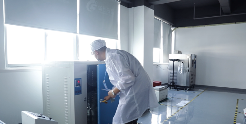
Verification should include ambient-light testing under controlled illuminance, reflectance measurement of the finished front stack, thermal soak tests at maximum ambient temperature, and accelerated aging with periodic luminance measurement. Results should be recorded as contrast ratio under defined illuminance rather than as luminance alone, because that is the metric that determines readability in the field.
Conclusion
A high-brightness LCD is not simply a brighter panel. Sunlight readability depends on the interplay between emitted luminance, front-surface reflectance, optical transmission, thermal behavior, and driver design. Engineers who evaluate these factors together, using contrast under realistic ambient light as the primary target, can build displays that remain legible and reliable in demanding outdoor environments throughout their service life.