Why Space Is the Hardest Specification in Commercial Equipment
Every commercial product eventually collides with the same physical reality: the enclosure is already designed, the PCB stack-up is already fixed, and the display—the one component the user actually looks at—is expected to fit into whatever volume remains. In handheld instruments, portable medical monitors, point-of-sale terminals, industrial handhelds, access-control panels, and compact benchtop analysers, the display aperture is often the tightest tolerance in the entire mechanical drawing. A standard catalogue module rarely lands inside that window without compromise.
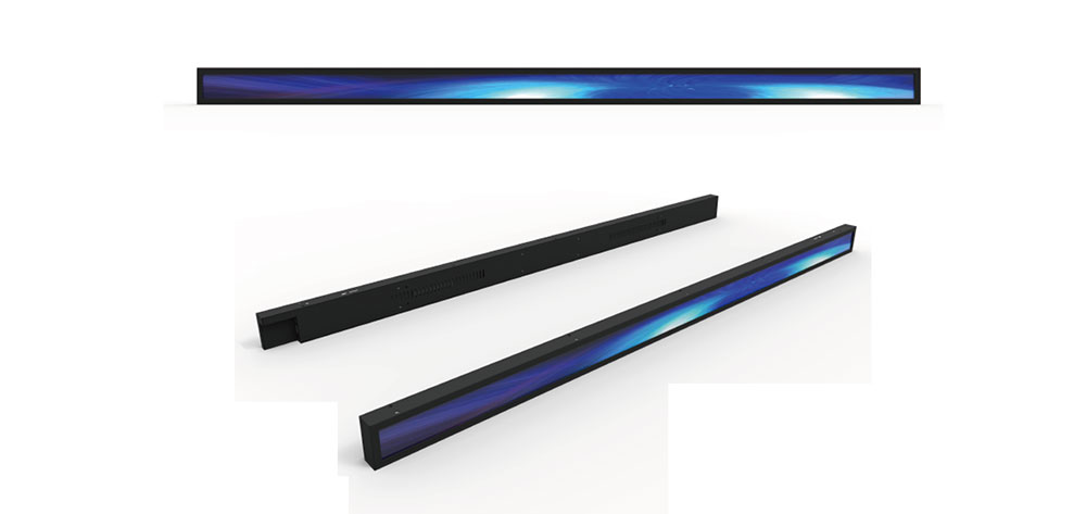
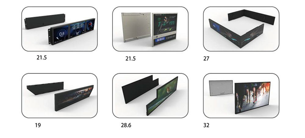
This is where custom LCD engineering earns its place. A custom display is not simply a standard panel with a different label; it is a co-designed optical, mechanical, and electrical subsystem built around the exact cavity, viewing geometry, power budget, and environmental profile of one product. For space-constrained equipment, customisation is less about aesthetics and more about reclaiming millimetres that off-the-shelf modules consume in bezel, connector height, backlight thickness, and flex routing.
The Anatomy of Display Volume: Where the Millimetres Actually Go
Designers frequently underestimate a display's true footprint because they measure the active area and forget everything orbiting it. A realistic volume budget must account for six separate regions:
- Active area — the pixels the user sees. Fixed by the required resolution and diagonal.
- Bezel — the border between active area and the outer edge of the glass. On commodity modules this can be 2–5 mm per side; on a custom design it can be reduced to well under 1 mm on selected edges.
- Driver and gate circuitry — the COG (chip-on-glass) region or COF (chip-on-film) tail. This is usually the widest edge and dictates where the flex exits.
- Backlight frame — the light guide, reflector stack, and LED carrier. Typically 1.5–3.5 mm thick, and highly tunable.
- Flex tail and connector — including the bend radius. A ZIF connector with a 0.5 mm pitch vertical entry can save 3–4 mm of depth compared with a right-angle header.
- Tolerances and assembly clearance — the working tolerance stack for adhesive, gasket compression, and pick-and-place placement.
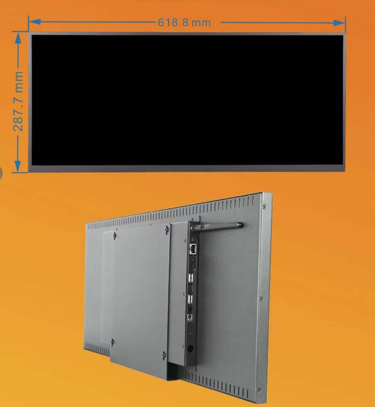
Custom engineering attacks all six. Reducing bezel width requires redesigning the seal and the routing of the ITO traces, which in turn may require narrowing the driver output pitch or moving to a different driver IC. That is a genuine engineering trade, not a catalogue option—and it is exactly the trade a custom display partner exists to make.
Matching the Mechanical Envelope: Glass Cutting, Thickness, and Seal Design
Custom LCDs are cut from standard glass masters, which means the outer dimensions can be tailored to the cavity rather than the cavity tailored to the module. Three levers matter most in tight enclosures.
Glass thickness. Standard TN and HTN cells are commonly 0.7 mm per plate; 0.55 mm and 0.4 mm substrates are available for thin profiles. Thinner glass reduces overall stack height but also reduces stiffness, so gasket compression forces must be re-checked—especially in products that are drop-tested or clamped by a front bezel.
Seal and edge geometry. The epoxy seal width sets the minimum practical bezel. A narrow-seal design with careful ITO routing can deliver a bezel under 1.0 mm on non-bonding edges, but it demands tighter cut tolerance and a review of moisture ingress performance. For equipment exposed to humidity or cleaning agents, the seal must be evaluated against the actual use environment rather than a generic rating.
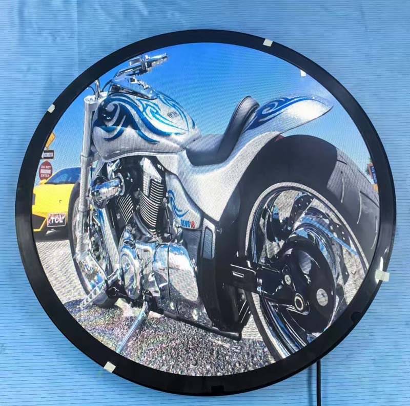
Corner and cutout shaping. Round corners, notches for a camera or sensor, and asymmetric outlines are all feasible with custom cutting. Asymmetric outlines are often the single highest-value change in handheld designs, because they let the display wrap around an internal feature that would otherwise force the whole product to grow.
Driving Pixels in a Small Footprint: COG, COF, and Interface Selection
The driver arrangement determines both the mechanical silhouette and the electrical architecture. In space-constrained commercial equipment, three configurations dominate:
Chip-on-glass (COG). The driver IC is bonded directly to the glass extension. This is the most compact and lowest-cost approach for segment, character, and small-to-medium graphic displays. It adds a glass "shelf" beyond the viewing area, but eliminates a separate PCB, which is often a net volume win.
Chip-on-film (COF). The driver sits on a polyimide film that folds behind the display. This allows the bezel on the bonding edge to shrink substantially and lets the electronics tuck under the panel—extremely valuable in devices under 10 mm thick. The cost is a more complex assembly and tighter control of the bend radius.
COG plus integrated controller with serial interface. For small TFT and graphic modules, an SPI or I²C interface with an integrated RAM buffer can reduce the host pin count to five or six lines. In a compact product where every connector pin costs board area and routing channels, this is often more consequential than raw bandwidth.
Interface choice should follow the mechanical constraint, not precede it. A parallel RGB interface needs 18–24 data lines plus timing signals and will force a wider flex and a larger connector; MIPI DSI or SPI collapses that to a handful of differential or serial lines and frees real estate. Where the host MCU is already committed, the display's bridge or controller should be chosen to match, even if that means a slightly higher unit cost.
Backlight Engineering for Slim, Bright, and Cool
High brightness and thin profiles are in tension: more light traditionally means more LEDs, a thicker light guide, or a larger optical cavity. For compact commercial equipment, the practical answers are edge-lit light guides with high-efficiency LED bins, optimised micro-structure patterns, and reflective films that recycle otherwise wasted light.
Three design notes are worth carrying into any space-constrained project:
- Brightness target versus thermal reality. A 1000 nit panel in a sealed handheld enclosure can raise the local ambient by 10–15 °C. Derating the LED drive current and specifying a higher-efficiency bin often yields better sunlight readability per watt than simply pushing current.
- Uniformity over peak. Hot spots near the LED entry edge look worse than a slightly dimmer, even field. Light guide design—not LED count—determines this.
- Optical bonding versus air gap. Bonding the cover glass to the LCD removes an internal reflection interface, improving contrast and reducing perceived washout under bright ambient light. It also removes a mechanical layer, saving 0.3–0.8 mm, but it complicates rework and must be assessed for thermal expansion mismatch.
Touch Integration Without Adding Depth
Adding touch to a compact device usually adds a sensor, an air gap, and a controller board. Three approaches keep the stack thin: on-cell or in-cell touch integrated into the display glass; a GFF or GF2 sensor laminated directly to the cover glass; or a resistive touch panel for applications where glove use, cost, and simplicity outweigh multi-touch. Each adds its own tolerance and its own failure mode, and the choice should be driven by the interaction the product actually needs rather than by defaulting to capacitive.
Where the front surface must be glass for chemical resistance or scratch durability, the cover glass, touch sensor, and display can be bonded into a single optical stack. This is the most volumetrically efficient architecture available, and it is where custom design delivers its clearest advantage over catalogue modules.
Electrical and Regulatory Considerations in Tight Enclosures
Miniaturisation concentrates electromagnetic problems. A display flex routed adjacent to a switching regulator or a radio module becomes both a victim and a radiator. Practical mitigations include ground-plane return paths on the flex, series termination at the source, ferrite beads on the backlight LED supply, and keeping the display's clock lines as short and as far from antenna structures as the layout permits.
Commercial equipment sold in the United States must satisfy FCC Part 15 requirements for unintentional radiators, and equivalent regimes apply in other markets. Displays contribute to radiated emissions primarily through their flex cables and through the backlight driver's switching node. Documenting the display's contribution during pre-compliance testing—rather than discovering it at final certification—saves both schedule and money. A custom supplier should be able to provide material declarations, RoHS and REACH statements, and test evidence for the specific configuration shipped, since a substitution in polariser, LED, or driver changes the EMC and reliability profile.
Environmental and Lifetime Requirements for Commercial Use
Commercial equipment is not always benign. Outdoor kiosks face UV and thermal cycling; medical carts face wipe-down chemicals; industrial handhelds face vibration and drop. Custom LCD design allows the polariser, seal, backlight films, and adhesive to be specified against the real exposure profile. Key parameters to define at the outset: operating and storage temperature range, UV exposure, chemical contact list, vibration and shock spectrum, and expected field life in hours. These inputs drive choices that cannot be retrofitted later—particularly polariser type, seal chemistry, and LED bin selection.
A Practical Customisation Workflow
Successful compact display projects follow a predictable sequence. Define the mechanical cavity and tolerance stack first, including gasket compression and connector bend radius. Then fix the optical requirement: luminance, contrast ratio, viewing angle, and colour performance under the actual ambient lighting. Only then select the driver, interface, and flex geometry, verifying that the chosen controller supports the resolution and refresh rate at the host's available bandwidth. Produce a drawing for approval covering outer dimensions, active area, viewing direction, bonding edge, flex exit and length, connector part number, and marking. Build prototypes for mechanical fit and optical validation before committing to tooling, and run a small pre-production batch for environmental and EMC confidence.
Documenting these decisions in a controlled drawing set is what separates a reliable custom display from an expensive one-off. The drawing becomes the contract between mechanical, electrical, and procurement teams, and it is the artefact that keeps production units identical to the sample that passed validation.
Conclusion
In space-constrained commercial equipment, the display is rarely the largest component but almost always the one with the least freedom. Custom LCD engineering converts that constraint into an advantage by treating bezel width, stack height, flex routing, backlight design, and interface selection as variables rather than fixed values. The result is a product that fits its enclosure without compromise, reads clearly in real ambient light, survives its actual environment, and reaches certification without surprises—outcomes that a catalogue module can only approximate.
KEYWORDS: custom LCD display, compact LCD module, high brightness LCD, COG COF display, space-constrained display design