Why the Bar Format Exists in the First Place
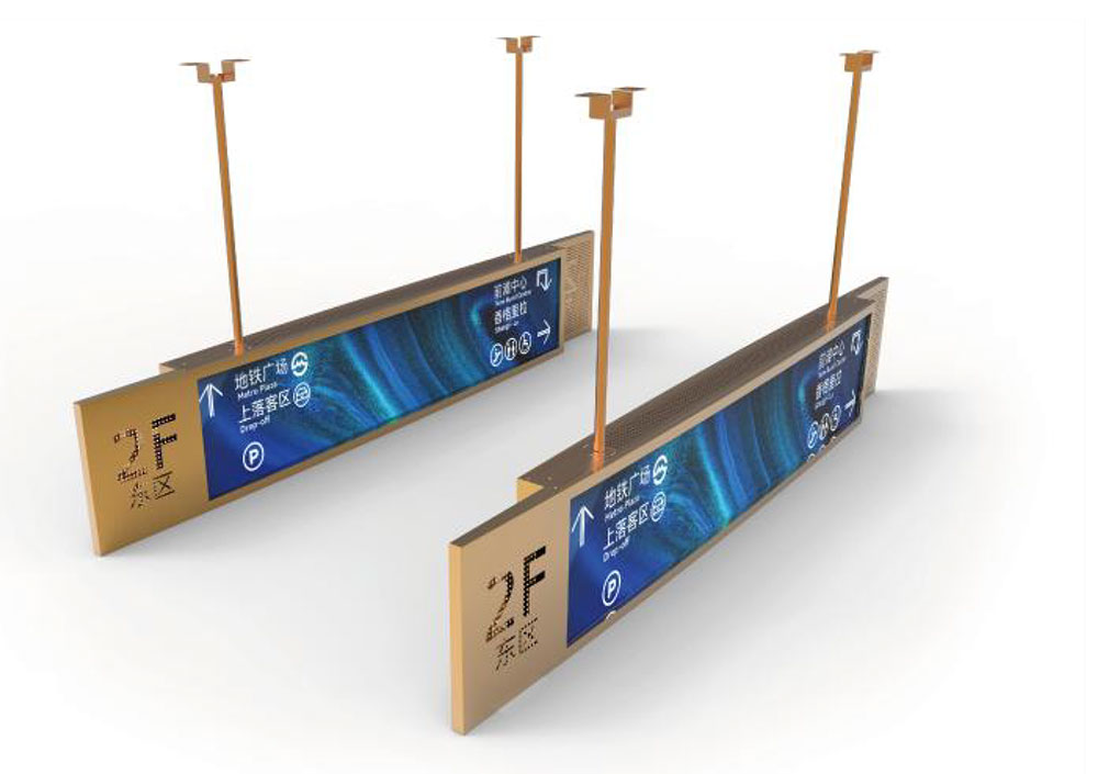
A bus information system is a set of very awkward rectangles. The overhead luggage-rack sign, the door-side next-stop panel, the driver's route display, the exterior destination board — none of them were designed around a 16:9 panel. They are long and shallow: a rack fascia that is 600 mm wide and 120 mm tall, a door pillar strip 40 mm across. For most of the digital-signage era, integrators filled that space with a standard 16:9 panel cropped by a black mask, wasting a large share of the module's area and its backlight power, or they stitched together several small modules with visible seams between them.
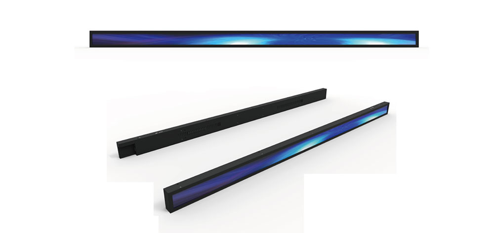
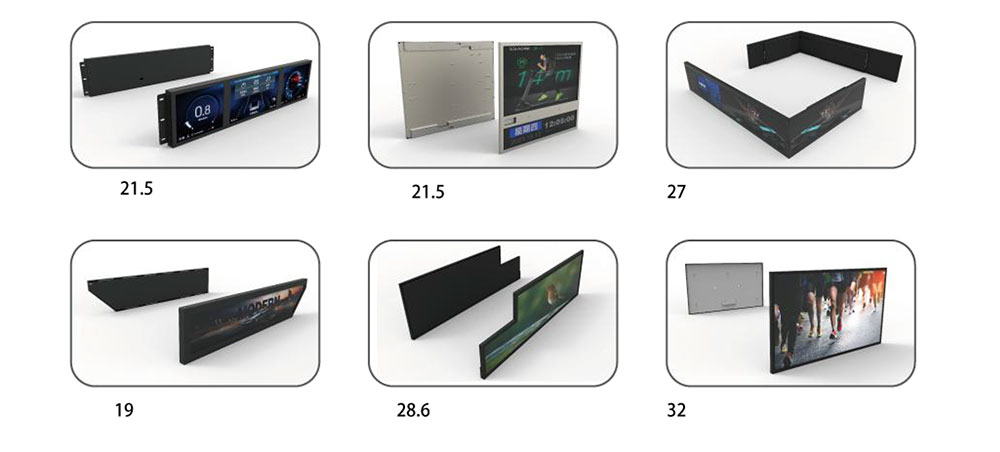
A bar type LCD — also called a stretched bar display, strip LCD, or ultra-wide bar panel — is a TFT module whose designed aspect ratio matches that geometry from the outset. Common formats run from roughly 8:1 and 16:3 through 29:9 and 37:9, in diagonal sizes from about 6 inches up to 50 inches and beyond. Because the panel is cut to the shape of the aperture and driven as a single piece of glass, you get one continuous image, one timing controller, one cable run, and no bezel cutting the content in half.
That said, "bar type" describes a shape, not a capability. Two modules with identical outlines may differ by a factor of four in brightness, by an order of magnitude in ruggedness, and completely in their long-term availability. The selection work is in the specification, not in the search filter. What follows is the order in which those specifications actually decide whether a design succeeds.
Step One: Fix the Geometry Against the Real Aperture
Start with the mechanical envelope of the vehicle, not with a catalogue. Measure the visible aperture after trim, the depth available behind the fascia, and the viewing distance range from the nearest seated passenger to the farthest standing one. Then derive three numbers:
- Active area and aspect ratio. A 29:9 panel matches a long, shallow signage strip; a 16:3 format suits a slightly deeper overhead panel. Choosing a ratio that is roughly the aperture's own avoids letterboxing and the dead black bands that look like a fault to passengers.
- Diagonal size versus pixel density. At a 1.5 m viewing distance, the eye resolves fine detail readily, so a 28-inch bar at 1920 × 360 will look sharp. At 4 m, the same panel reads as coarse. Match resolution to distance rather than to the marketing sheet.
- Depth budget. Bar modules are thin, but the backlight diffuser, the driver board, the mating connector and the cable bend radius all consume depth. A 12 mm module with a right-angle LVDS connector and a 30 mm bend radius needs closer to 30 mm of clear space behind the glass.
Also confirm the mounting datum. Bar panels are long and therefore mechanically flimsy in the middle. If the module's frame offers fixing points only at the two ends, the centre of a 700 mm strip will flex with vehicle vibration, and flexing glass eventually cracks or delaminates the polariser. Ask for the frame's fixing-hole pattern and confirm there are centre supports, or plan a compliant mounting bracket that carries the middle of the module.
Step Two: Brightness Is Only Half the Sunlight Story
Every integrator asks for nits first. Luminance matters, but on a bus the readable quantity is contrast under reflected light. Sunlight through a window can put several thousand lux on the glass, and a glossy front surface reflects a few percent of it straight back at the viewer. A 1000-nit panel behind a glossy cover can be less legible than a 700-nit panel behind a properly treated one.
Targets that hold up in service
- Interior, shaded, no direct sun: 400–500 cd/m² is normally sufficient.
- Interior with direct low-angle sun through side glazing: 700–1000 cd/m², and this is where a high-brightness backlight earns its cost. Note that raising LED drive current to reach these levels also raises heat, which is the subject of a later section.
- Exterior destination boards and door-side panels exposed to daylight: 1000–1500 cd/m² or higher, plus an anti-reflective front surface, plus a bonded cover glass.
The three levers, in order of effectiveness
Optical bonding. Laminating the cover glass to the panel with an optical adhesive removes the air gap that produces the strongest internal reflection. The gain in contrast under bright light is large — often more visible than a 30 percent brightness increase — and it also improves impact resistance and eliminates condensation fogging in the gap. If a supplier offers only a frame-and-gasket assembly for a sunlit application, that is a warning sign.
Anti-glare versus anti-reflective treatment. An anti-glare (AG) etch scatters reflections into a soft haze, which preserves readability of the whole image but slightly softens fine text. An anti-reflective (AR) coating suppresses the reflection amplitude instead, keeping the image crisp, and is generally preferable where small route text or a QR code must remain resolvable. Many good outdoor bar displays combine both.
Native contrast and black level. Legibility of light text on a dark route map depends on how dark the dark can get. A panel with 1000:1 native contrast and good black uniformity beats a brighter panel with grey blacks. Ask for a uniformity measurement across the full length of the bar — long panels are prone to brightness roll-off and colour shift at the ends, because the LED light bar feeds the diffuser from a long distance and small variations accumulate.
Step Three: Resolution, Content Format and the Aspect-Ratio Trap
Bar panels come with unusual native resolutions — 1920 × 360, 1920 × 540, 2880 × 640, 3840 × 720 and similar. Confirm the exact native timing and the supported refresh rates before you commit, and confirm them again at the controller side. A very common integration failure is a media player whose scaler does not offer that timing, so the image is stretched or letterboxed and the installed result looks amateur.
Check three things in writing:
- Native resolution and the exact pixel clock, plus whether the module accepts a reduced blanking variant.
- Whether the scaler in your player supports arbitrary custom timings or only CEA/VESA standards.
- Whether the panel's driver IC handles non-native input gracefully, since a marginal timing produces a rolling or clipped image rather than a clean fallback.
Text-driven content — stop names, announcement tickers — also argues for a specific pixel structure. RGB vertical stripe sub-pixels render small text far better than the various sub-pixel-sharing arrangements used to cut cost. If passengers must read a stop name at a glance from three metres, ask about the sub-pixel layout, not just the resolution.
Step Four: Thermal Behaviour Decides Field Reliability
A bus is a thermal environment of extremes. A vehicle parked in the sun with the HVAC off can reach 70 °C or more at the top of the cabin; a vehicle operating through a northern winter can sit below −20 °C overnight. High-brightness backlights make it worse, because a bar module concentrates a lot of LED power into a narrow strip with limited surface for dissipation.
- Operating temperature range should be stated for the complete module, not only the panel glass — the LED driver, the timing board and the connector all have their own limits, and the electrolytic capacitors on a cheap driver board are usually the first component to fail in heat.
- Ask for the thermal design. An aluminium back frame that spreads LED heat along the length of the bar is materially different from a plastic housing. For sealed exterior units, ask how heat reaches the outside — a rear heat-spreader to a metal enclosure wall, or a fan, which brings dust and a wear-out mechanism with it.
- Cold-start behaviour. Below about −20 °C, liquid crystal response slows dramatically and the image smears. Either specify a panel rated for the cold, or specify a heater and, importantly, the warm-up delay the system must allow before displaying safety-critical information. A destination board that shows a grey smear for two minutes after a cold start is a real operational problem, not a cosmetic one.
- Condensation. Sealed housings that breathe through temperature cycling trap moisture. Specify the sealing strategy — gasket compression values, a breathable membrane vent, desiccant where appropriate — and make sure the front surface is heated or bonded so fog does not form on the inside of the cover.
Step Five: Vibration, Shock and Impact Ratings That Mean Something
Road vibration is a broadband, continuous input; potholes and kerb strikes are the shock events. A bar module's long lever arm amplifies both. The relevant specifications are the ones tied to a test standard with a named severity, not a marketing adjective.
| Concern | What to require | Why it matters on a bus |
|---|---|---|
| Random vibration | A stated profile and duration, referenced to an automotive or rail vibration standard, tested in the mounting orientation | Continuous road input fatigues solder joints and connector contacts over years |
| Mechanical shock | A stated acceleration and pulse width, applied along all three axes | Kerb strikes and speed humps deliver the peak loads |
| Front-surface impact | A quantified IK rating on the finished assembly | Passengers lean on panels, cleaning equipment strikes them, and vandalism is a real cost line |
| Connector retention | Locking connector with a specified retention force; strain relief on the cable | The single most common field failure in signage is a partially backed-out LVDS connector |
Two mechanical details deserve explicit attention. First, the bonding between the cover glass and the panel: a fully bonded stack is stiffer and much more impact-tolerant than an air-gap assembly, and it also stops glass shards from entering the cabin if the cover breaks. Second, the interaction between the module and the vehicle structure: bolting a rigid bar to a flexing body panel transmits body flex straight into the glass. A compliant interface — rubber-isolated inserts, slotted holes, a slightly flexible bracket — is usually the difference between a design that survives ten years and one that cracks in the first winter.
Step Six: Interfaces, Dimming and Electrical Discipline
Bar modules are available with LVDS, eDP, MIPI DSI, and parallel RGB interfaces. On a vehicle, LVDS and eDP dominate, because they tolerate longer cable runs with better immunity. Decide the interface by the harness length and the EMC environment, not by what your prototype board happens to expose.
- Cable length and shielding. LVDS over a metre in a noisy electrical bay needs a shielded twisted-pair harness with the shield bonded at the display end. Specify the maximum supported length from the panel supplier and derate it.
- Dimming. Automatic dimming is essential for a bus: a panel set for daylight is blinding at night and a panel set for night is unreadable at noon. Confirm the dimming method and the low-end behaviour. PWM dimming is efficient but can produce visible flicker or beat against a camera-based driver-monitoring system; check the PWM frequency and, for night mode, whether the driver can shift to a higher frequency or to analogue dimming. Also confirm the minimum usable duty cycle, since many backlights lose linearity or colour stability at very low levels.
- Power. Vehicle supplies are dirty. Specify the operating voltage window including cranking transients, and require reverse-polarity and load-dump protection on the display's own input where the architecture allows it. A 24 V bus system can see transients well beyond nominal.
- EMC. The display must not interfere with the vehicle's radio and must survive the vehicle's own emissions. Require EMC test evidence against the automotive EMC standards your vehicle type approval references, and note that the cable is part of the antenna — a compliant module with a badly routed harness still fails.
Step Seven: Lifetime, Luminance Depreciation and Availability
Backlight lifetime is usually quoted as time to a percentage of initial luminance — commonly 50,000 to 70,000 hours to 70 percent, under specified drive and temperature conditions. Read the conditions. A lifetime figure quoted at 25 °C ambient with reduced drive current may bear no relation to a sealed enclosure at 60 °C running at full brightness, where the real figure can be a fraction of the headline number.
Plan for depreciation rather than failure: an LED backlight does not usually die, it dims. If the design has no headroom, a panel specified at exactly 700 cd/m² will fall below the legibility threshold well before it fails. Choosing 1000 cd/m² and running at 70 percent drive gives both margin and cooler operation.
Supply chain matters as much as physics. Public transport equipment has a service life of a decade or more, and consumer-grade bar panels are frequently discontinued within two to three years. Ask for a written longevity commitment, the current lifecycle status, and a drop-in replacement path with an identical mechanical footprint. A pin-compatible successor defined at the design stage is worth more than a small unit-price saving.
Step Eight: Certifications and Documentation to Request Up Front
Which approvals apply depends on the vehicle class and the market, but a serious supplier will already hold the evidence. Ask for:
- Environmental and vibration test reports, with the test standard, severity and duration named.
- EMC test reports relevant to automotive or rail vehicle installation.
- Flammability and smoke documentation for materials used in the passenger compartment, in the form the local approval body requires.
- RoHS and REACH declarations, and a materials declaration for the full bill of materials.
- Ingress protection rating for sealed assemblies, tested on the finished unit rather than inferred from the panel.
- Optical measurement data: brightness across the bar, uniformity map, contrast, colour coordinates and their tolerance, and viewing-angle behaviour.
- A drawing package with tolerances, the fixing pattern, the connector part number and the mating half.
Do not accept a datasheet that reports only typical values. The difference between typical and minimum brightness is where field complaints come from; require the minimum, and require it measured on the finished bonded assembly rather than on bare glass.
Pull-It-Together Selection Checklist
| Parameter | What to specify | How to verify | |||||||
|---|---|---|---|---|---|---|---|---|---|
| Format & active area | Ratio matched to aperture; single continuous panel | Mechanical drawing checked against the trimmed opening | |||||||
| Brightness | Minimum, not typical, in cd/m², at the assembly level | Luminance measurement at several points along the bar | |||||||
| Optical stack | Bonded cover glass with AR and/or AG treatment | Cross-section drawing plus a reflection measurement | |||||||
| Uniformity & colour | Stated percentage across the full length; colour tolerance in a defined space | Uniformity map supplied with the sample | |||||||
| Thermal | Module-level operating range; heater and warm-up time if cold-rated | Chamber test report on the complete unit | |||||||
| Mechanical | Vibration, shock, IK rating; centre fixings; compliant mount | Test reports plus a physical flex check on the sample | |||||||
| Electrical | Interface type, max harness length, dimming method and frequency, transient protection | EMC report plus a bench test with the actual harness | |||||||
| Lifetime | Hours to defined lum KEYWORDS: How to Choose a Bar Type LCD Display for Bus Information Systems
Document Official InformationDocument Type: Official Product Technical Specification
Last Updated: 11, 05, 2026
Author: Product Engineer / R&D Specialist--YUN CHEN
Approved By: Technical Director / Quality Supervisor--HUA CHEN
LinkedIn: https://www.linkedin.com/in/hua-chen-b25a2a40a/
Experience: 12+ years in optical bonding and high-brightness backlight design for outdoor and industrial LCD applications.Chen has led the optical bonding process development at HITULCD since 2018,
working directly with clients across Europe on wide-temperature and
sunlight-readable display projects, including outdoor signage and
transit display deployments.
Global Product Certifications & Compliance DocumentsOur full product lineup has passed internationally recognized quality compliance testing. Our manufacturing system follows standardized strict control procedures with fully traceable quality records and verifiable test data. All official certificates are available to support project evaluation and procurement inspection.
CE Certification
Download Full Test Report PDF
FCC Certification
Download Full Test Report PDF
RoHS Compliance
Download Full Test Report PDF
ISO9001 Quality Management System
Download System Audit Report PDF
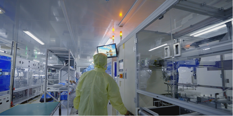
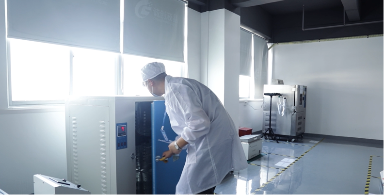
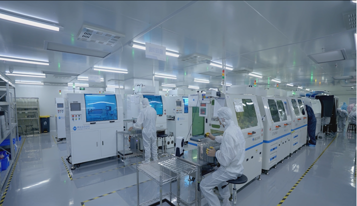
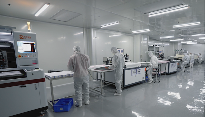
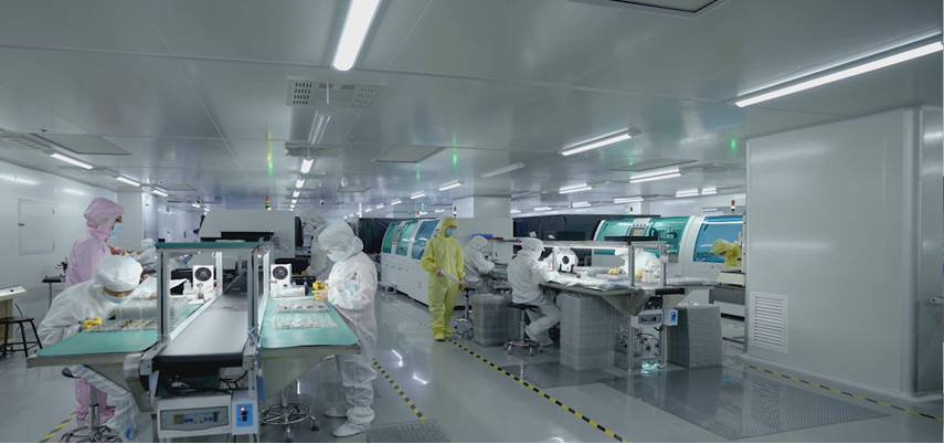
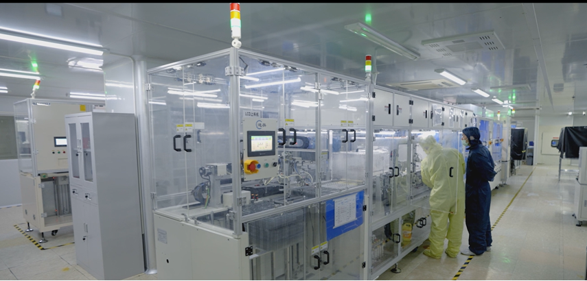
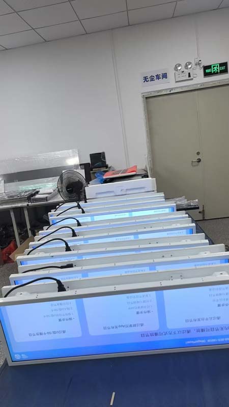
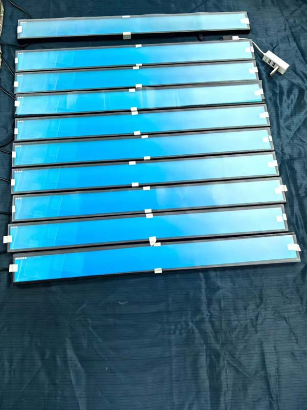
Real Factory Workshop Footage · In-House Production & Strict QC AssuranceWe are a direct OEM manufacturer with self-owned standardized production facilities, fully automatic SMT assembly lines, professional aging test workshops and precision quality control labs. All manufacturing procedures are completed in-house with multi-stage quality inspections. No third-party intermediaries to guarantee consistent product performance and stable delivery schedules. A Real Factory. Publicly Verifiable.Before you send an inquiry, check us out yourself. All the information below is on public record with Chinese government business registries.
✓ We maintain full transparency on all official company filings held by Chinese government regulators. If you’d like to confirm our physical factory location ahead of discussions, our registered address is fully searchable on Google Maps.
View On Google Maps →
Popular Articles
| ||||||||