Outdoor displays face a problem that indoor displays rarely encounter. Direct sunlight can exceed 100,000 lux at ground level, and the light reflecting off the screen surface can wash out the image entirely. A display that looks crisp in an office can become unreadable on a roadside kiosk, a marine console, or a vehicle dashboard at midday. Sunlight readability is therefore not a single specification. It is the result of coordinated decisions in backlight design, optical stack construction, thermal management, and brightness control. This article explains how high-brightness LCDs achieve readability in outdoor conditions, which parameters matter most, and how to verify performance before deployment.

Why Sunlight Readability Is Difficult
The core challenge is contrast. A display forms an image by modulating light that travels from its backlight through the liquid crystal layer and out to the viewer. Ambient light also travels in the opposite direction. It enters through the front glass, reflects off internal layers, and returns to the eye. This reflected ambient light adds a veil of brightness to the black areas of the image, and that veil lowers the contrast ratio. If the reflected light is strong enough, dark pixels look gray and the image loses its meaning.
Contrast under ambient light can be expressed as the ratio between the luminance of white and black states, with reflected ambient light added to both. In a dim room, a standard display with 300 cd/m² output may achieve a comfortable contrast ratio. Under full sun, the reflected component can be tens or even hundreds of times larger than the display's own black level. Raising the backlight output helps only if the panel's internal reflections are also controlled. A common design target for sunlight-readable displays is a sustained contrast ratio of at least 3:1 under the specified ambient condition, though requirements vary by application and by the test standard used.
Measuring Brightness and Contrast Under Sunlight
Display luminance is measured in candela per square meter, also written as cd/m² or nits. Indoor monitors often operate between 250 and 400 nits. High-brightness LCDs for outdoor use commonly range from 1,000 to 2,500 nits, and some specialized units exceed that level. Higher output is necessary but not sufficient. Engineers must evaluate three values together: peak luminance, black-state luminance, and reflectance.
Reflectance describes how much ambient light the front surface and internal layers return to the viewer. It is usually reported as a percentage of incident light. A bare glass surface reflects roughly 4 percent of incident light at each air-glass interface, and a panel with several uncoated interfaces can reflect a significant fraction of incoming sunlight. Reducing reflectance is therefore as important as increasing brightness.
When testing, the measurement environment should reflect the intended use. Lab measurements at a fixed illuminance can be useful for comparison, but they should be paired with simulated outdoor conditions, including the angle of incidence of the sun, the spectrum of daylight, and the illuminance level. Manufacturers often report readability under a specified illuminance, such as 20,000 or 50,000 lux, and users should confirm which condition applies to their installation.
Backlight Engineering
The backlight determines the display's maximum luminance and largely sets its energy consumption and lifetime. Most high-brightness LCDs use edge-lit or direct-lit LED arrays. Direct-lit designs place LEDs behind the panel and can deliver high luminance with better local uniformity, while edge-lit designs use a light guide to produce thinner modules at moderate brightness.
Achieving very high luminance requires more than adding LEDs. The LED drive current must be balanced against heat, because LED efficiency falls as junction temperature rises. The optical design must also collimate or diffuse light efficiently so that less energy is wasted. Reflective films, prism sheets, and diffusers each affect how much light finally exits through the liquid crystal layer. A well-designed backlight directs light toward the viewer with minimal loss, which reduces the number of LEDs needed for a given output.
Color and uniformity also matter. Outdoor displays are often used for navigation, signage, or instrumentation, where a color shift or dim corner can cause confusion. Engineers should specify luminance uniformity across the active area, typically measured at nine or more points, and check that the white point stays stable as the backlight dims.
Panel Optics and Surface Treatment
Above the backlight, the optical stack determines how much light reaches the viewer and how much ambient light returns. The polarizers, color filters, and cover glass all contribute. High-transmittance polarizers and optimized color filters increase the amount of backlight that exits the panel. This matters because every percentage point of lost transmittance must be compensated by higher backlight power.
Surface treatment is the main tool for controlling reflections at the front face. Anti-glare coatings diffuse reflected light, which reduces the mirror-like image of the environment but can soften text and slightly blur fine detail. Anti-reflection coatings use thin-film interference to cancel part of the reflected light, reducing reflectance with less blur. Many outdoor products combine anti-reflection coatings with a low-reflectance cover treatment and select the coating type based on the expected viewing angle and the sharpness the application requires.
Optical bonding is another important technique. In an air-gap display, the cover glass is separated from the LCD by a layer of air, which creates two additional reflecting surfaces. Filling the gap with optically clear adhesive removes those interfaces, reduces internal reflection, and improves contrast. Bonding also improves resistance to condensation and dust ingress, which is useful for outdoor enclosures. The tradeoff is cost, rework complexity, and the need for careful process control to avoid bubbles and delamination.
Thermal Management
A high-brightness display dissipates a large amount of heat, and that heat has several effects. LED efficiency decreases as temperature rises, the liquid crystal response slows at low temperatures and can change at high temperatures, and polarizers and adhesives can degrade over time if they remain hot for long periods. Outdoor installations add further thermal stress from solar loading. A dark enclosure exposed to sunlight can reach internal temperatures well above the ambient air temperature.
Thermal design typically combines heat-spreading materials, metal chassis that act as heat sinks, and in some cases forced air or closed-loop cooling. The goal is to keep LED junction temperature within a range that preserves luminance and lifetime. Engineers should also consider the ambient temperature range specified for the product and confirm performance at both the lower and upper limits. Warm-up behavior is important as well. Some systems reach full brightness only after the backlight stabilizes, and the control software should account for that behavior.
Brightness Control, Ambient Light Sensing, and Power
A sunlight-readable display does not need to run at maximum brightness at all times. Doing so wastes power, generates heat, and can cause discomfort or glare in shaded conditions. Most outdoor displays therefore use an ambient light sensor to adjust backlight output automatically. The sensor measures the surrounding illuminance, and the controller selects a backlight level that keeps the contrast ratio within the target range.
Good control design includes smooth transitions so the image does not flicker when clouds pass or when the display moves between shade and sunlight. Pulse-width modulation is common for dimming, but the PWM frequency must be high enough to avoid visible flicker and to prevent interference with cameras or other sensitive equipment. Some designs use constant-current driving at lower brightness levels to avoid flicker altogether. The sensor itself must be placed where it sees the same light as the viewer, not the direct sun falling on the display, and it should be calibrated against a reference meter.
Power budgeting follows directly from the brightness target. A display that runs at 2,000 nits draws far more power than one at 500 nits, which affects battery sizing in mobile systems and thermal load in enclosed systems. Designers should model the expected duty cycle, including the proportion of time spent at peak brightness, so the power supply and thermal design reflect real operation.
Validation and Testing
Verifying sunlight readability requires a test plan that goes beyond a single luminance measurement. A useful plan includes luminance and uniformity measurements at multiple points, reflectance measurement with a calibrated light source, contrast testing under simulated sunlight, and environmental testing across temperature, humidity, and vibration. For optically bonded products, testing should also check for delamination, bubbles, and changes in color or transmittance after thermal cycling.
Readability should be assessed with real content, not only test patterns. Engineers can evaluate small text, icons, and color indicators under the target illuminance, because those elements reveal problems that a full-white test pattern may hide. Viewing angle should also be tested, since reflections and contrast change as the observer moves off-axis. Finally, long-duration tests at high brightness help reveal backlight degradation, thermal stress, and adhesive aging before the product reaches the field.
Deployment Considerations
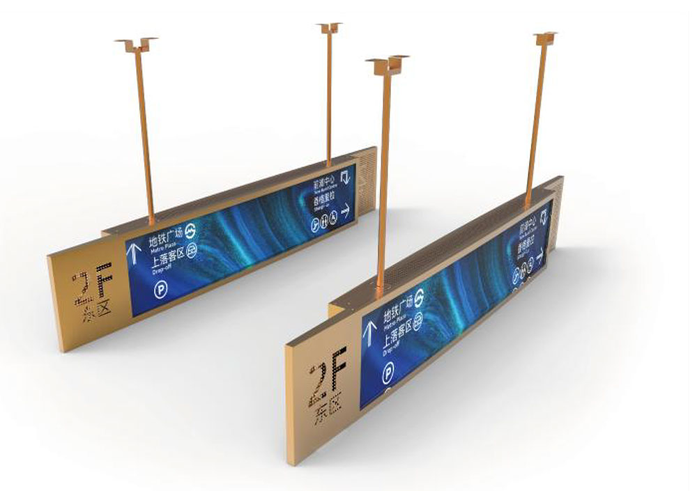
Successful outdoor deployment depends on how the display is mounted and oriented as much as on its specifications. Mounting angle affects how sunlight strikes the screen and how reflections reach the viewer. Shading, such as a hood or canopy, can reduce direct solar exposure and lower the brightness the display must reach to remain readable, which also reduces thermal load. Enclosures should provide the appropriate ingress protection rating and manage condensation, especially in regions with large day-night temperature swings.
Installers should also verify that the display's brightness settings match the environment after installation. A unit that was set up indoors may appear too dim outdoors or too bright at night. Commissioning should include a readability check under the actual lighting conditions at the installation site, at the times of day when visibility is most critical.
Conclusion
Sunlight readability is the result of a complete system. High luminance from the backlight is necessary, but it must be combined with low reflectance in the optical stack, effective thermal management, and intelligent brightness control. Engineers should evaluate peak luminance, black-state luminance, and reflectance together, test under conditions that match the intended use, and design for long-term thermal and optical stability. When these elements work together, a high-brightness LCD remains clear and legible in full sunlight, and it does so without wasting power or compromising lifetime.
KEYWORDS: high-brightness LCD, sunlight readable display, outdoor LCD, display nits, anti-reflection optical bonding