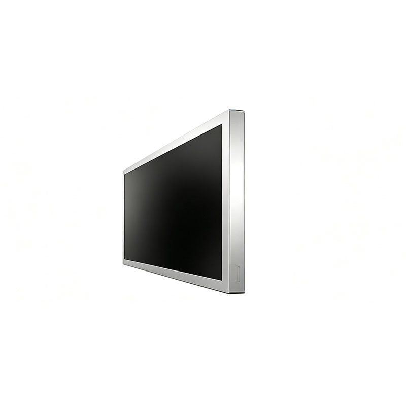
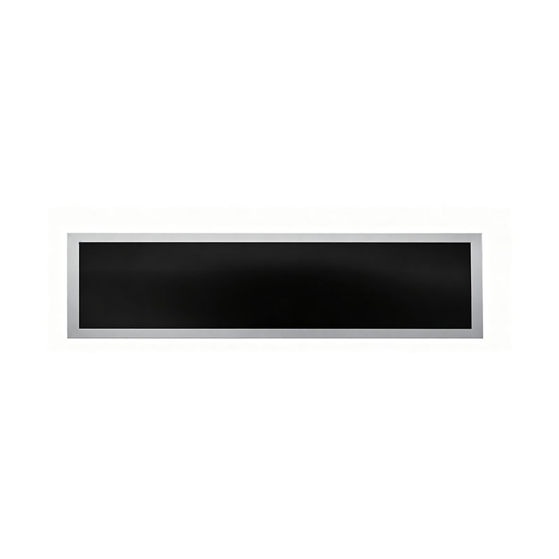
16.2 Inch Shelf Edge Bar LCD Display
MODEL: HT162HBM
Need customized solution?
Our engineering team is always ready to provide you with professional technical support and flexible customized services.
Understand light customization servicesBuilt by us. Configured for you.
HITULCD supplies LCD modules and display solutions directly from our manufacturing operation, giving OEMs, integrators and distributors direct access to engineering, customization and production.
Supply
Supplier Qualification
VerificationTechnical Specifications
| LCD PANEL PARAMETERS | DRIVER BOARD SPECIFICATIONS | ||
|---|---|---|---|
| ITEM | DETAILS | ITEM | DETAILS |
| Model Number | HT162HBM | Input Interface | LVDS, 30 Pins |
| Brand | HITULCD | Signal Type | LVDS |
| Product Series | 18.5" Cut Panel Series | OSD KEYS | Depends on LVDS controller |
| Diagonal Size | 16.2" Cut Stretched Bar (Cut from 18.5" Panel, 1/5 Cut) | OSD CONTROL | Depends on LVDS controller |
| Resolution | 1366 × 159, Aspect Ratio 8.59:1 (>3:1) | ||
| Product Category | Graphic Type Display | ||
| Panel Type | a‑Si TFT‑LCD, Complete LCM Module | ||
| Physical Shape | Flat Rectangle | ||
| Display Area (A.A) | 409.8(W) × 46.08(H) mm | ||
| Overall Dimension | 439.8(W) × 76.08(H) mm | ||
| Max Thickness | 20 mm | ||
| LCD Technology | IPS, Transmissive Polarizer | ||
| Typical Brightness | 1000 NITS (Adjustable range: 300~1000 NITS) | ||
| Transmissive Contrast Ratio | 1000:1 (Typ.) | ||
| Viewing Angle | 89°/89°/89°/89°(Min.)(L/R/U/D) | ||
| Viewing Direction | Full Viewing Angle | ||
| Display Colors | 16.7M Colors | ||
| Backlight Type | WLED | ||
| Touch Panel | Without Touch Function | ||
| Application Fields | Digital Signage, Cut Stretched Bar Displays | ||
| Operating Temperature | 0 ~ 50 °C | ||
| Storage Temperature | -20 ~ 70 °C | ||
OEM / ODM Custom-Cut LCD Displays: Any Size, Built to Your Enclosure
Your space defines the display, not the other way around. We resize, re-seal and re-assemble TFT-LCD panels to the exact dimensions your project needs, from a compact 8" strip to a wall-length 88" bar.
Can't find a standard display that fits your shelf, cabinet, kiosk or vehicle interior? Send us your target dimensions. We will tell you within 2–3 working days how we can build it.
Why Custom Cutting?
Standard LCDs come in a handful of fixed formats such as 16:9 and 16:10. Real-world installations rarely do. Shelf rails, vending fronts, elevator strips and control-panel recesses are long, narrow and non-standard.
Instead of redesigning your product around a stock panel, we cut the panel to fit yours:
Any aspect ratio: from 3:1 up to 32:1 and beyond
Any practical size: from about 8" to 88" diagonal, or defined directly by width × height in millimeters
Free choice of cutting axis and margin: planned around your bezel, bracket and mounting design
Lower cost and faster lead time than fully custom-tooled panel development
"Any size" means we start from your dimensions, not from a catalog. Every request goes through a free feasibility review to confirm the cut is safe for the panel's array, seal and driver layout before we quote.
Market Applications We Build For
| Market | Typical requirement | Typical custom format |
|---|---|---|
| Retail & Supermarkets | Shelf-edge price and promotion strips that match shelf length | Long, slim bars sized to shelf rails (e.g., 16"–48") |
| Vending & Self-Service | Front-panel information strip above or beside product windows | Custom width to fit the machine front |
| Transportation | Passenger information above doors, in aisles and on elevator strips | Ultra-wide, high-brightness, wide-temperature |
| Industrial & HMI | Narrow status and control strips embedded in cabinets | Small, ruggedized, optically bonded, touch-enabled |
| Hospitality & Signage | Menu boards, wayfinding and architectural recess displays | Non-standard ratios to fit walls and fixtures |
| Gaming & Entertainment | Marquee, header and button-deck displays | Compact bars with high contrast and brightness |
OEM vs. ODM: Choose Your Level of Involvement
OEM: You Supply the Design, We Build It
You give us the specification and drawings. We manufacture to your requirements under your brand.
Custom size, resolution, brightness and interface
Your logo, labeling, packaging and documentation
Build-to-print manufacturing with controlled incoming inspection and outgoing QC
Stable, repeatable supply for long-lifecycle programs
ODM: We Co-Develop the Solution
You tell us the application and the constraints. Our engineering team designs the display module with you.
Panel selection and cutting-line planning
Backlight, light-guide and driver-board design for the new outline
Mechanical design: bezel, bracket and housing
Optional touch, optical bonding, media player and CMS integration
Design-for-manufacturing review to protect yield and cost
What We Can Customize
| Category | Options |
|---|---|
| Size & shape | Any width × height within feasibility limits, custom aspect ratio, custom bezel width |
| Resolution | Matched to the cut panel or re-mapped by driver board |
| Brightness | 500 / 700 / 1,000 / 1,500 nits and above |
| Interface | LVDS, eDP, MIPI, HDMI driver boards |
| Touch | Projected capacitive (PCAP), with cover glass |
| Surface | Anti-glare, anti-reflective, anti-fingerprint, optical bonding |
| Environment | Wide-temperature (−20 to +70 °C), conformal coating |
| System | Android / Linux media player, CMS integration, Wi-Fi / 4G |
| Branding | Private label, custom packaging, custom firmware boot logo |
Our Cutting & Sealing Capability
Two cutting methods: mechanical scribe-and-break for cost-efficient programs; ultrafast laser cutting for tight tolerances and minimal edge damage
Layout-safe planning: cut lines are placed only in safe border areas, clear of Gate/Source routing, the TFT array and the seal line
Edge finishing: microscope inspection, with optional edge grinding
Secondary sealing: UV-curable adhesive dispensing and full polarizer re-lamination to protect against moisture and LC leakage
Optical control: backlight matched to the new outline, edge Mura and light-leakage inspection
Reliability validation: high/low-temperature, 85 °C/85 % RH humidity, thermal shock, vibration and drop tests, based on IEC and ISTA standards
From Idea to Mass Production in 6 Steps
Submit your requirement: target size, brightness, interface, quantity and environment
Feasibility review: cutting-line drawing and risk assessment in 2–3 working days
Quotation & sample plan: NRE, unit price, lead time and acceptance criteria
Engineering samples: typically 20 pcs, with approval sheet and test data
Pilot run: process validation and yield report
Mass production & delivery: EXW / FOB / DDP, with consistent QC and traceability
Typical timing: samples in about 15–25 working days, mass production about 30–45 days after sample approval. MOQ starts from 50 pcs for custom-cut sizes.
Why Partner With Us
Engineering-led: you talk to engineers who understand panel structure, not only sales
Transparent process: documented cutting, sealing and inspection steps you can audit
Flexible volumes: from prototype lots to recurring mass-production programs
Global-ready: CE, FCC, RoHS and REACH support, plus export packaging and documentation
Long-term support: lifecycle management, spare parts and after-sales service
Start Your Custom Display Project
Send us the following and we will reply with a feasibility assessment:
Target dimensions (W × H) and tolerance
Brightness, interface and touch requirements
Operating environment
Estimated annual volume
Panel model or drawings, if available
[Request a Free Feasibility Review] [Download OEM/ODM Brochure]
Custom-cut availability depends on panel model and layout feasibility. Final specifications, pricing and lead time are confirmed in the quotation and sample approval sheet.
16.2" Stretched Bar LCD Display for Shelf-Edge & Space-Constrained Integration
Industrial-grade, custom-cut TFT-LCD module | OEM/ODM | LVDS / eDP | Optional touch, optical bonding & high brightness
Engineered for OEMs, system integrators and retail-technology project teams who need an ultra-wide display that fits where a 16:9 panel cannot, with documented cutting, sealing and reliability processes you can audit before you commit to volume.
1. Product Overview
The 16.2" Stretched Bar LCD is an ultra-wide TFT-LCD module with an aspect ratio of roughly 5.7:1. It is built by precision-resizing a mainstream-panel open cell, then re-sealing, re-polarizing and re-assembling it with a matched backlight and driver board.
The result is a slim, long-format display for shelf edges, vending and kiosk fronts, elevator and transit strips, cabinet recesses and industrial control consoles, at a cost and lead time well below a fully custom-tooled panel.
Typical applications
| Sector | Use case |
|---|---|
| Retail / Smart Store | Shelf-edge pricing, promotions, ESL-alternative video shelf strips |
| Vending & Self-Service | Front-panel information strips, product showcase bars |
| Transportation | Bus / rail passenger information, elevator door strips |
| Industrial & HMI | Narrow control-panel status displays, cabinet-embedded UI |
| Hospitality & Commercial | Wayfinding, menu boards, architectural signage recesses |
2. Key Specifications
Values marked † are typical reference values for this display class. Final figures are confirmed in the formal datasheet and sample approval sheet for your project.
| Parameter | Specification |
|---|---|
| Screen size | 16.2 inch (diagonal) |
| Aspect ratio | ~5.7:1 (custom ratios available) |
| Active area (W × H) | ≈ 405 × 71 mm † |
| Resolution | 1366 × 238 † (custom on request) |
| Panel type | TFT-LCD, IPS / ADS wide-angle |
| Viewing angle | 178° / 178° (H/V) † |
| Brightness | 500–700 cd/m² standard; 1,000+ cd/m² optional |
| Contrast ratio | 1000:1 typ. † |
| Color depth | 16.7 M (8-bit) † |
| Backlight | Edge-lit LED, 50,000 h typ. lifetime † |
| Interface | LVDS or eDP (MIPI / HDMI driver-board options) |
| Touch (optional) | Projected capacitive (PCAP), 10-point |
| Surface options | Anti-glare, anti-reflective, anti-fingerprint |
| Optical bonding (optional) | OCA / OCR full lamination |
| Operating temperature | 0 to +50 °C standard; −20 to +70 °C wide-temp option † |
| Storage temperature | −20 to +60 °C standard † |
| Humidity | 10–90 % RH non-condensing (operation) |
| Power supply | 12 V DC (driver board) † |
| Certifications | CE, FCC, RoHS, REACH (per project scope); UL / IEC 62368-1 support on request |
| Lifetime | 50,000 h typ. |
3. Why Engineers Choose Our Cut-Panel Bar Displays
Fits real-world envelopes. Ultra-slim profile, narrow bezel options, and custom mounting brackets for shelf rails and cabinet cut-outs.
Documented process control. Cutting, edge finishing, sealing and inspection follow a controlled, traceable route card, not an ad-hoc rework step.
Brightness headroom. 500–1,000+ nits options, with an integrated heat-spreader design for high-brightness builds. If you place a cover glass in front of the display, plan for roughly 8–12 % luminance loss.
Integration-ready. Standard LVDS/eDP, optional Android or Linux media players, and support for the CMS of your choice.
Low-risk prototyping. Engineering samples first, then pilot run, then mass production, each with defined acceptance gates.
4. Technical Process & Feasibility (Engineering FAQ)
4.1 Cutting method, tolerance and layout feasibility
Which cutting method do you recommend?
The method is chosen per panel model and target dimension:
| Method | Typical tolerance† | Edge quality† | Best for |
|---|---|---|---|
| Mechanical scribe-and-break (diamond wheel) | ±0.10 mm | Chipping typically ≤ 100 µm | Cost-optimized volume programs, straight cuts, standard glass thickness |
| Ultrafast (picosecond) laser cutting | ±0.03 – 0.05 mm | Chipping typically ≤ 20 µm, minimal micro-cracks | Tight-tolerance, narrow-margin, or thin-glass projects |
Our engineering team recommends a method after reviewing your panel drawings and target dimensions.
Will the cut interfere with Gate / Source routing or the TFT array?
Cut lines are planned only through the dummy / non-functional border area, away from the active array, the gate/source fan-out wiring, and the sealant line. A cut is feasible only if there is sufficient safe margin between the cut line and the active-area seal. Our standard design rule is to keep the cut line clear of the seal and array edge by the manufacturer-specified minimum, and we verify this with an overlay drawing before any glass is cut.
What do we need from you for a feasibility review?
Open-cell or panel model number (and manufacturer, if known)
Panel mechanical drawing and target outline dimension with tolerance
Panel specification sheet (resolution, interface, pin definition)
Target active-area size and required bezel/border widths
Integration drawing (housing, bracket, cover glass) if available
If panel array/layout drawings are not available from the panel maker, we assess feasibility via microscope inspection and sample verification.
Turnaround: feasibility feedback with a cutting-line overlay drawing is typically provided within 2–3 working days after receiving the above.
4.2 Edge finishing
Post-cut edge inspection under microscope (typically 50–100×) on sampled and first-article units
Edge chipping, micro-crack and corner-damage limits are defined per drawing and agreed at sample approval
Optional edge grinding/chamfering to relieve stress concentration
Cleaning and defect screening before the sealing step
5. Reliability & Sealing Assurance
5.1 Edge sealing process
A cut exposes the liquid-crystal cell edge, so we treat re-sealing as a critical process:
Secondary sealing with UV-curable epoxy / acrylic adhesive, applied by controlled dispensing
Moisture-barrier and low-ionic-content sealant selection to prevent LC contamination and moisture ingress
Controlled UV + thermal curing profile
Full re-lamination of polarizers with edge overlap
100 % in-line visual inspection of seal continuity, plus leak and moisture-ingress screening on sampled units
5.2 Reliability testing
Our cut modules are validated against industry-standard test methods. Reference test plan for industrial / commercial-grade projects (final conditions can be aligned with your specification):
| Test | Reference standard | Typical condition† |
|---|---|---|
| High-temperature storage | IEC 60068-2-2 | +60 °C, 240–500 h |
| Low-temperature storage | IEC 60068-2-1 | −20 °C, 240–500 h |
| High-temp / high-humidity ("85/85") | IEC 60068-2-78 | +85 °C / 85 % RH, 240–500 h (non-operating); +60 °C / 90 % RH operating |
| Thermal shock | IEC 60068-2-14 | −30 °C ↔ +70 °C, 30 min dwell, 100 cycles |
| Vibration | IEC 60068-2-64 | 5–500 Hz random, 3 axes |
| Mechanical shock | IEC 60068-2-27 | 50 G / 11 ms, 3 axes |
| Packaged drop | ISTA 2A / ISO 2248 | 1.0 m, 10 drops |
| ESD | IEC 61000-4-2 | ±8 kV contact / ±15 kV air |
Test reports for comparable cut-panel projects, including 85/85 humidity and thermal shock data, can be shared under NDA. Pass criteria are defined per project: no seal failure, no LC leakage, no functional failure, and optical parameters within agreed drift.
5.3 Optical performance: light leakage and color shift
Cutting and re-sealing are controlled to avoid edge Mura and light leakage:
Backlight and light guide are matched to the new outline, not just trimmed
Light-shielding tape and reflector edge design to prevent edge light leakage
Uniformity checked at 9-point / 13-point measurement (typical ≥ 80 % luminance uniformity†)
Edge color-shift and Mura inspection at 100 % on first articles, AQL sampling in mass production
Edge-zone acceptance criteria are documented in the sample approval sheet
6. Cost, Yield & Lead Time
Ranges below are indicative for this product class. A firm quotation is issued after feasibility review.
| Item | Typical range† |
|---|---|
| NRE / engineering fee | Project-dependent (cutting fixtures, drawings, backlight and bracket tooling). Typically refundable or credited against the first mass-production order above agreed volume |
| Prototype quantity | 20 pcs standard first sample lot (smaller lots possible) |
| Prototype lead time | About 15–25 working days after drawing and feasibility freeze |
| Pilot run | 100–200 pcs, ~3–4 weeks |
| Mass production lead time | About 30–45 days after PO and sample approval |
| MOQ | 50 pcs for custom-cut ratios; lower for standard catalog sizes |
| Expected yield | Pilot stage: ~85–92 %. Mature mass production: ≥ 95 % target (final-inspection basis) |
| Warranty | 12–24 months, depending on contract |
Yield drivers we manage: cut-line margin, glass thickness, sealing consistency and post-cut handling. We share yield data and root-cause reports after each build stage.
7. Customization Options
Size, aspect ratio and resolution (custom cuts on OEM orders)
Brightness: 500 / 700 / 1,000 / 1,500 nits
Interface: LVDS, eDP, MIPI, HDMI driver boards
Touch: PCAP with cover glass, optional glove / wet-touch tuning
Optical bonding, AG / AR / AF coatings, conformal coating
Wide-temperature (−20 to +70 °C) versions
Bezel, bracket, housing and cable/connector customization
Android / Linux media player and CMS integration
8. Integration Notes
Leave at least 2–3 mm clearance around panel edges for thermal expansion and cable routing.
For models above 1,000 nits, provide ventilation or heat-spreader contact.
Account for 8–12 % luminance loss when using a front cover glass.
Use shielded LVDS/eDP cable, ≤ 30 cm recommended, to maintain signal integrity and EMC compliance.
Refer to the mechanical drawing for the FPC bending radius and connector orientation.
9. Ordering Workflow
Send your requirements: panel/size target, brightness, interface, quantity, environment
Feasibility review: cutting-line drawing and risk assessment (2–3 working days)
Quotation & sample agreement: NRE, price, lead time
Engineering samples: approval sheet and test report
Pilot run: process validation and yield report
Mass production & shipping: Incoterms EXW / FOB / DDP available
10. Request a Quote or Engineering Review
Please include the following to speed up feasibility review:
Target size / aspect ratio and tolerance
Brightness, interface and touch requirements
Operating environment (temperature, humidity, indoor/semi-outdoor)
Estimated annual volume and first-order quantity
Panel model number and drawings, if you have them
[Request Datasheet & Sample Quote]
Specifications may be improved without notice. Typical values (†) are for reference; final specifications are confirmed in the approved product datasheet and sample approval sheet.
Know The Terms Before You Inquire.
|
01 — Shipping Terms
Incoterms Available
EXW
Ex Works — pick up from our factory
FOB
Free On Board — most common for ocean freight
CIF
Cost, Insurance & Freight — to your port
|
02 — Order Minimum
MOQ: 1 Units
Applies to standard specs. Custom brightness, cutting or bezel may adjust MOQ, confirmed at quotation. Sample units available before bulk order
|
03 — Payment Protection
Multiple Secured Methods
|
A Real Factory. Publicly Verifiable.
|
Legal Company Name
Shenzhen Hantu Jiashi Technology Co., Ltd.
|
Unified Social Credit Code
91440300306068446B
|
|
Legal Representative
YUN CHEN
|
Registered Capital
RMB 2,000,000
|
|
Established
May 23, 2014 (11+ years operation)
|
Business Status
● Active / In Operation
|
|
Registered Factory Address
Building B, Gangshen Innovation Park, Huaning Road, Dalang Sub-district, Longhua District, Shenzhen, Guangdong, China
|
|
Contact HITULCD
We'll respond via email within 24 hours. If you'd like to discuss details over WhatsApp or a call, please leave a preferred time and contact method in your message — we will never call you unannounced.
Related solutions
This product is suitable for the following industry application scenarios
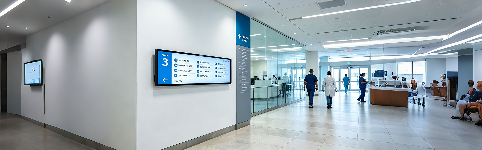
Floor Information Bar LCD Display Solution
Ultra-wide, high-brightness stretched bar LCD disp...
view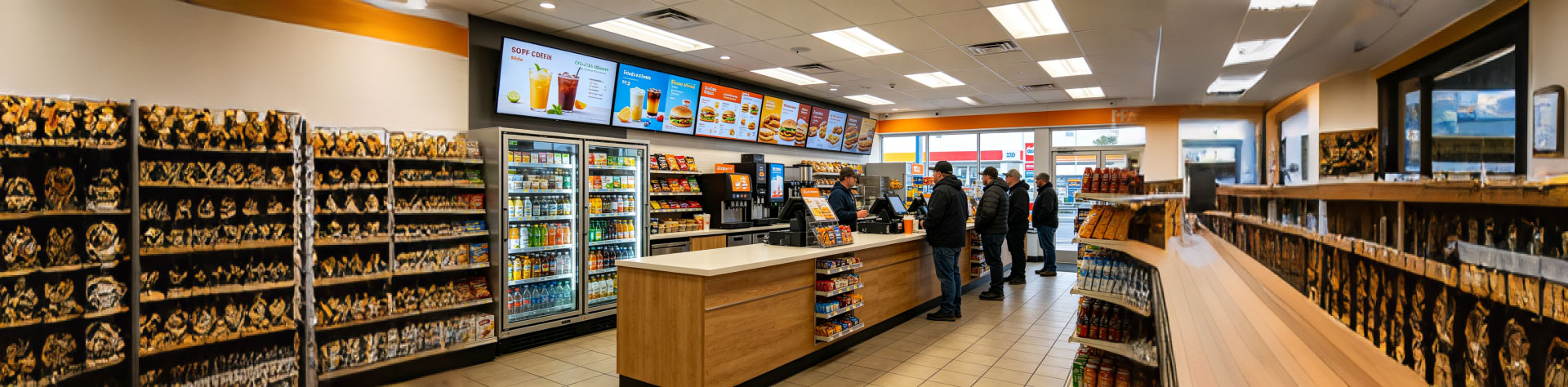
Convenience Store Bar LCD Display Solution
Ultra-slim, high-brightness stretched bar LCD disp...
view
Bus Passenger Information Stretched Bar Display Solution
A rugged, ultra-wide stretched bar display solutio...
viewRelated Products
You may also be interested in the following products