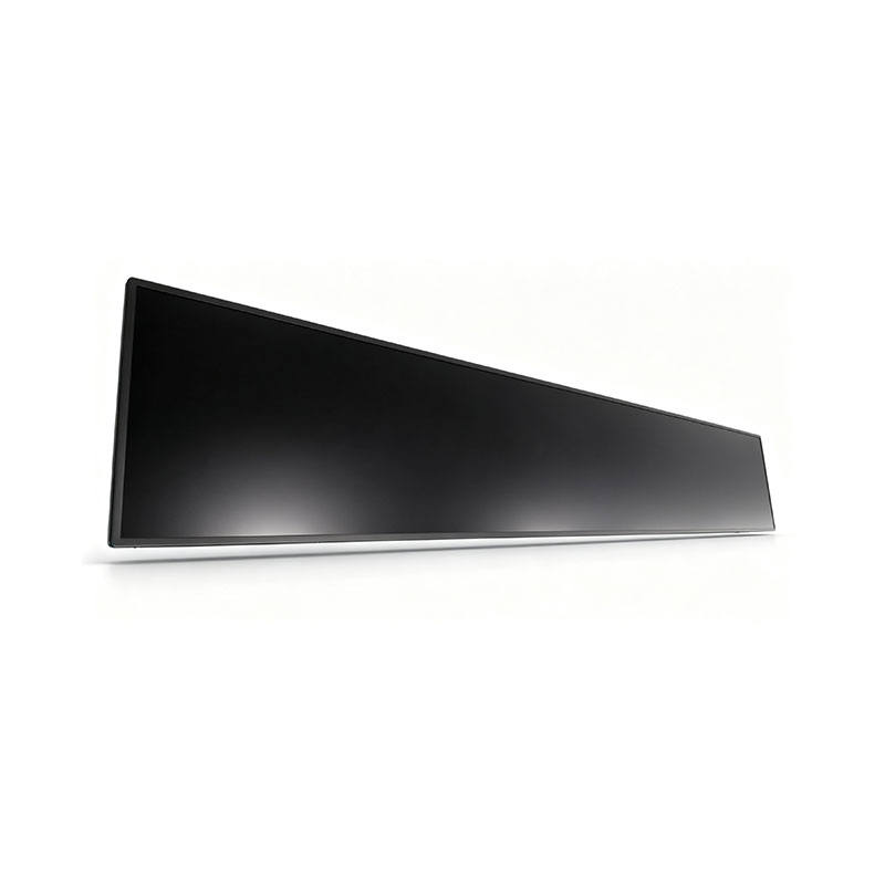
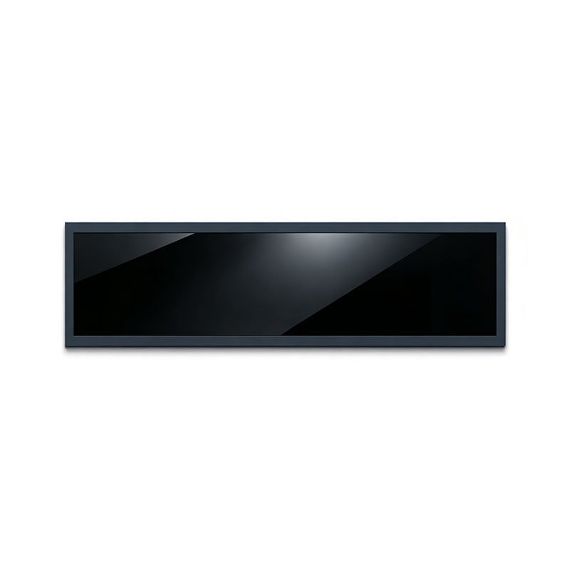
58.4 Inch Stretched LCD Panel for Narrow Display Applications
MODEL: P584KVN01. 1
Need customized solution?
Our engineering team is always ready to provide you with professional technical support and flexible customized services.
Understand light customization servicesBuilt by us. Configured for you.
HITULCD supplies LCD modules and display solutions directly from our manufacturing operation, giving OEMs, integrators and distributors direct access to engineering, customization and production.
Supply
Supplier Qualification
VerificationTechnical Specifications
| LCD PANEL PARAMETERS | HDMI/CONTROL BOARD SPECIFICATIONS | ||
|---|---|---|---|
| ITEM | DETAILS | ITEM | DETAILS |
| Model Number | P584KVN01.1 | Input Interface | Require special eDP 4‑Lanes driver board(NOT LVDS / V‑by‑One) |
| Manufacturer | HITULCD | Power Input | DC 12V‑5A |
| Diagonal Size | 58.4" Cut‑Type Stretched Bar (65" panel 1/2 cut, Not Native Panel) | OSD KEYS | Depends on eDP controller |
| Resolution | 3840(RGB) × 1080 DFHD, 3.56:1 | OSD CONTROL | Depends on eDP controller |
| Panel Type | a‑Si TFT‑LCD, LCM | ||
| Pixel Arrangement | RGB Vertical Stripe | ||
| Display Area(A.A) | 1428.48(W)×401.76(H) mm | ||
| Overall Dimension | 1456.28(W)×429.56(H)×28(D) mm | ||
| Panel Weight | 9.20Kgs (Typ.) | ||
| Surface Treatment | Matte (Haze 28%), Hard Coating (3H) | ||
| Contrast Ratio | 5000:1 (Typ.)(Transmissive) | ||
| Typical Brightness | 700 NITS | ||
| Response Time | 16 (Typ.)(G to G) ms | ||
| LCD Technology | AMVA3, Normally Black, Transmissive | ||
| Viewing Angle | 89°/89°/89°/89°(Typ.)(CR≥10) | ||
| Viewing Direction | Full Viewing Angle | ||
| Display Colors | 1.07B Colors,72% NTSC | ||
| Refresh Rate | 60Hz | ||
| Backlight Type | WLED,50K Hours,With LED Driver | ||
| Power Consumption | - | ||
| Signal Interface | 51 pins,0.5 mm eDP (4 Lanes) (NOT LVDS / V‑by‑One) | ||
| Supply Voltage | 12.0V (Typ.) | ||
| Touch Panel | Without Touch Function | ||
| Application Fields | Industrial Equipment,Digital Signage,Vehicle Displays | ||
| Operating Temperature | -25 ~ 60 °C | ||
| Storage Temperature | -25 ~ 60 °C | ||
| Important Remark | Uses eDP 4‑Lanes interface, regular LVDS/V‑by‑One controller board CANNOT work directly,special eDP driver board is mandatory. It is cut‑type panel (65‑inch TV panel 1/2 cut), not native stretched‑bar panel,support‑25℃ ultra‑low‑temp operation.Compare with P584KVN01.0:changed to eDP‑4Lanes interface,contrast upgraded to 5000:1,thickness 28mm. | ||
OEM / ODM Services for Custom-Cut Stretched Bar LCD Panels
Market Demand & Customer Analysis for Overseas Partners
1. Why OEM/ODM Demand Is Growing in This Category
Stretched bar / cut LCD panels are, by nature, a non-standard product — no two installations have identical space constraints, so almost every serious order eventually needs some level of customization. This is different from commodity monitor categories where a buyer can select from a fixed catalog. Three market forces are driving OEM/ODM inquiries specifically:
Fragmented end-use environments. Shelf-edge signage, elevator/corridor strips, transit destination signs, and control-room bars each impose different outline dimensions, mounting methods, and viewing conditions — a catalog SKU rarely fits without modification.
Brand and system differentiation. Digital signage integrators and kiosk/AV companies want their own housing design, bezel branding, and control board/firmware so the hardware matches their software platform (CMS) and doesn't look like a reseller product.
Supply chain consolidation. Buyers increasingly prefer a single manufacturing partner who can take a project from panel-cutting through mechanical housing, driver board, and final assembly — rather than sourcing a bare cut panel from one factory and outsourcing enclosure/integration elsewhere.
2. Customer Segment Analysis
| Segment | Typical Need | OEM vs ODM Fit |
|---|---|---|
| Digital signage integrators / AV system houses | Bare panel or panel+driver board in specific size, to slot into their own enclosure and CMS software | Usually OEM — they supply mechanical/electrical spec, we manufacture to it |
| Kiosk & vending machine manufacturers | Fully finished stretched display module (panel + housing + control board) matching their machine's cutout | Often ODM — they give a target dimension and use-case, we design and engineer the full module |
| Transportation / rolling-stock builders | Ruggedized, wide-temperature, vibration-tested bar displays certified to rail/transit standards | ODM with reliability engineering — customer specifies certification target, we design and validate to it |
| Retail chains / brand owners (direct) | A private-labeled, ready-to-install shelf display with their own branding on bezel/packaging | ODM + private label — full design, our factory, their brand |
| Distributors / resellers in NA & EU | Small-to-mid volume, standard-ish sizes with minor tweaks (interface, brightness, bezel color) for a regional catalog | Light-OEM — configuration from existing tooling rather than new cut lines, to keep MOQ and lead time down |
Understanding which bucket a given inquiry falls into early (via the drawing/spec exchange described in the previous product document) determines whether the project needs new cutting tooling (higher NRE, longer lead time) or can be configured from an existing cut-line and housing family (fast turnaround, lower MOQ).
3. What Can Be Customized (OEM) vs. Fully Designed (ODM)
OEM — you specify, we build to your spec
Outline dimensions, active area, and aspect ratio (within feasible cut-line range)
Brightness tier and backlight type (standard, sunlight-readable, ultra-high-bright)
Interface (HDMI / DP / LVDS / V-by-One) and driver board feature set
Operating temperature range and sealing/reliability grade
Mechanical interface: VESA mount pattern, open-frame vs. chassis, bezel dimensions
Cable, connector, and power input type to match your existing system
ODM — we design based on your use-case and constraints, you brand it
Full mechanical housing design (aluminum/steel chassis, IP-rated enclosure, anti-glare/anti-vandal front glass)
Embedded media player or Android board integration, with your CMS pre-loaded
Custom control board (OSD logic, remote monitoring, RS232/network control) built for your feature list
Packaging, user manual, and bezel branding under your company name
End-to-end reliability validation package matched to your target certification (CE/FCC/EN50155, etc.)
Most real projects sit somewhere between the two — e.g., a customer OEMs the panel/cut-size decision but asks us to ODM the housing and firmware. We scope this per project rather than forcing a binary OEM/ODM label.
4. Engagement Workflow
Requirement intake — use-case, target dimension/aspect ratio, volume forecast, and whether you need bare panel, module, or finished unit
DFM & feasibility review — as covered in the product feasibility document; determines new-tooling vs. existing-tooling path
Design proposal — for ODM projects, we return a mechanical/electrical design proposal and 3D rendering for sign-off before tooling starts
Sample build (T0) — typically 20 pcs, validated against your spec and reliability requirement
Pilot run & yield confirmation — small batch (typically 100–500 pcs) to lock in process yield before full MP release
Mass production — with agreed QC gate (AQL sampling, burn-in, or 100% functional test per your requirement)
5. Commercial Considerations for OEM/ODM
| Factor | OEM (existing-tooling / configure-to-order) | ODM (new design / new tooling) |
|---|---|---|
| NRE | Low to none if within existing cut-line family | Higher — covers mechanical/electrical design and new tooling |
| Sample lead time | 1–3 weeks | 3–6 weeks, depending on housing/board complexity |
| MOQ | Lower — can often start at small-batch trial orders | Higher — needed to amortize design and tooling investment |
| IP / exclusivity | Design typically shared across customers unless exclusivity is negotiated | Can be built as an exclusive design/tooling for your brand, under agreement |
We're happy to discuss volume-based NRE waivers or tooling-amortization-into-unit-price arrangements for buyers who want to avoid a large upfront design fee — this is a common structure for distributors and regional brand owners entering a new market segment.
6. Recommended Next Step for OEM/ODM Inquiries
To scope your project correctly from the first call, please share:
Target end application and customer-facing brand (yours or your end customer's)
Whether you need a bare panel, a panel+driver module, or a fully housed unit
Estimated annual volume and target unit cost
Any certification/standard you must meet (CE, FCC, EN50155, IP rating, etc.)
Whether branding/private-label packaging is required
This lets us route your inquiry to the right engagement model (light-OEM configuration vs. full ODM design) and quote NRE, lead time, and MOQ accurately rather than giving a generic range.
58.4″ Custom-Cut Stretched Bar LCD Panel
Technical & Commercial Overview for Overseas Engineers, Procurement Managers & Project Owners
1. Product Summary
The 58.4″ stretched bar panel is produced by precision-cutting a standard mother TFT-LCD glass into an ultra-wide, narrow-format panel to fit space-constrained installations — shelf-edge signage, transit displays, elevator/corridor screens, POS bars, and control-room strip displays.
Because this is a custom-cut product rather than a native panel off a fixed production line, the specifications below (aspect ratio, brightness, resolution, backlight configuration) are engineered per project, based on the source panel your team specifies or that we recommend. This document is written to directly answer the technical due-diligence questions that engineering and sourcing teams typically raise before committing to a cutting project.
| Item | Typical Range (project-dependent) |
|---|---|
| Diagonal size | 58.4″ (custom cut) |
| Source panel options | 55″ / 58″ FHD or 4K commercial-grade TFT panels (BOE / CSOT / LG / AUO, subject to availability) |
| Achievable aspect ratio | From 16:3 up to 16:6, tailored to your cut window |
| Brightness | 500–2,500 nits (standard to sunlight-readable, backlight-dependent) |
| Interface | LVDS / V-by-One / eDP, HDMI or DP via driver board |
| Backlight | Direct-lit or edge-lit LED, MTBF ≥ 50,000–100,000 hrs |
| Operating temp | 0–50 °C standard; -20–70 °C wide-temp option |
Note: Exact numbers depend on the source mother glass and your target cut dimensions. We provide a confirmed spec sheet after DFM (Design for Manufacturability) review of your drawing.
2. Process Feasibility & Engineering Assessment
Cutting method — mechanical wheel scribing vs. laser cuttingWe select the cutting method based on your tolerance and edge-quality requirements, not a fixed default:
Mechanical scribe-and-break (diamond wheel): lower cost, faster turnaround, suitable for tolerances of ±0.3–0.5 mm. Preferred for high-volume, cost-sensitive orders.
Ultra-fast (picosecond/femtosecond) laser cutting: cold cutting process, minimal micro-crack propagation, holds tighter tolerances (±0.1–0.2 mm), and is the recommended route when the cut line runs close to active circuitry or when edge strength under vibration is critical (transportation, industrial).
We will recommend the appropriate method once we see your target dimensions and tolerance callouts.
Trace and array clearanceEvery cut line is checked against the panel's Gate/Source driving layout and TFT array boundary before quoting. Cutting through active gate or source lines will disable rows/columns, so our engineering team maps a keep-out zone around the array edge and, where the requested dimension would intrude into active circuitry, we propose the nearest feasible cut line or a gate-driver re-routing/COF re-bonding solution.
What we need from you to run a feasibility check:
Target outer dimensions and active area (H × V), with tolerance
Preferred source panel model, or your resolution/brightness/interface requirements so we can select one
Mounting/bezel constraints (VESA, embedded, open-frame)
Environmental conditions (indoor/outdoor, temperature range, vibration/shock exposure)
Sample quantity and target unit cost, if available
With this, we return a DFM feasibility report — including a marked-up cut-line drawing against the source panel's array map — typically within 3–5 working days.
Edge quality standardCut edges are inspected under microscope against an internal standard for chip size, edge flatness, and micro-crack length before the sealing step; panels outside spec are scrapped at this stage rather than passed downstream, so micro-cracks don't propagate later under thermal cycling.
3. Reliability & Edge-Sealing Assurance
Sealing processAfter cutting and edge grinding/polishing, the exposed liquid-crystal cell edge is resealed to restore moisture and liquid-crystal-leakage protection. Depending on panel structure and customer reliability targets, we apply:
UV-cure edge sealant (dispensed) — standard for most commercial-grade projects, cured under controlled UV dosage for consistent bond strength
Frame/structural sealing — an additional mechanical edge frame or potting compound for panels going into outdoor or high-vibration housings, giving a secondary moisture barrier on top of the UV seal
The sealing method is specified per project based on your operating environment and target certification level.
Reliability testingCut-and-sealed modules go through the same reliability program as standard TFT modules, scaled to consumer-grade or industrial-grade acceptance criteria as required:
Damp heat (double 85: 85 °C / 85 %RH) — typically 96–500+ hrs depending on grade
High/low temperature storage & operating cycling
Thermal shock cycling (e.g., -20 °C ↔ 60 °C, multiple cycles)
Mechanical drop / structural shock testing for the finished module or housing
We can share representative test reports and pass/fail data from prior cutting projects of comparable size and aspect ratio under NDA — please specify your required test standard (e.g., IEC 60068 series, or an internal customer spec) so we send the matching dataset rather than a generic one.
Optical performance at the cut edgeTwo failure modes are specifically monitored at the resealed edge:
Light leakage at the border of the active area, caused by backlight escaping through an imperfect seal or misaligned optical film after re-cutting the backlight stack
Mura / color shift near the edge, typically from uneven sealant thickness or optical film shrinkage during cure
Our process controls (backlight film re-trimming to match the new cut line, controlled UV cure profile, and 100% edge-region optical inspection) are designed to keep both within acceptable Mura standards for signage-grade viewing; a mura sample/report can be provided for your specific size before mass production sign-off.
4. Cost, Yield & Lead Time
| Stage | Typical Range | Notes |
|---|---|---|
| NRE (tooling & process setup) | Project-dependent — quoted after DFM review | One-time; based on cut-line complexity and fixture requirements |
| First sample (T0, ~20 pcs) | Typically 3–5 weeks from confirmed drawing | Includes cutting, sealing, driver board integration, and reliability spot-check |
| Mass production yield | Commonly in the 85–95% range | Depends on cut length, aspect ratio severity, and source panel batch quality; confirmed after pilot run |
| MOQ | Project-dependent | Lower MOQs available for standard aspect ratios using existing tooling; new custom cut lines carry a higher MOQ to amortize NRE |
Because yield, NRE, and MOQ are all a function of the specific cut geometry and source panel, we provide firm numbers only after the feasibility review in Section 2 — this avoids quoting a generic figure that doesn't reflect your actual dimensions.
5. Recommended Next Step
To move from inquiry to a formal quotation, please send:
Target outline dimensions / active area drawing (DWG/DXF or PDF)
Required brightness, resolution, and interface
Application environment (indoor/outdoor, temp range, expected vibration/shock)
Reliability/certification standard you need to meet
Sample and mass-production volume expectations
Our engineering team will return a DFM feasibility report, recommended cutting method, and budgetary quotation (NRE, sample lead time, expected MOQ) within 3–5 working days of receiving the above.
This document is a general technical overview for evaluation purposes. Final specifications, tolerances, and test data are confirmed in a project-specific datasheet after DFM review.
Know The Terms Before You Inquire.
|
01 — Shipping Terms
Incoterms Available
EXW
Ex Works — pick up from our factory
FOB
Free On Board — most common for ocean freight
CIF
Cost, Insurance & Freight — to your port
|
02 — Order Minimum
MOQ: 1 Units
Applies to standard specs. Custom brightness, cutting or bezel may adjust MOQ, confirmed at quotation. Sample units available before bulk order
|
03 — Payment Protection
Multiple Secured Methods
|
A Real Factory. Publicly Verifiable.
|
Legal Company Name
Shenzhen Hantu Jiashi Technology Co., Ltd.
|
Unified Social Credit Code
91440300306068446B
|
|
Legal Representative
YUN CHEN
|
Registered Capital
RMB 2,000,000
|
|
Established
May 23, 2014 (11+ years operation)
|
Business Status
● Active / In Operation
|
|
Registered Factory Address
Building B, Gangshen Innovation Park, Huaning Road, Dalang Sub-district, Longhua District, Shenzhen, Guangdong, China
|
|
Contact HITULCD
We'll respond via email within 24 hours. If you'd like to discuss details over WhatsApp or a call, please leave a preferred time and contact method in your message — we will never call you unannounced.
Related solutions
This product is suitable for the following industry application scenarios
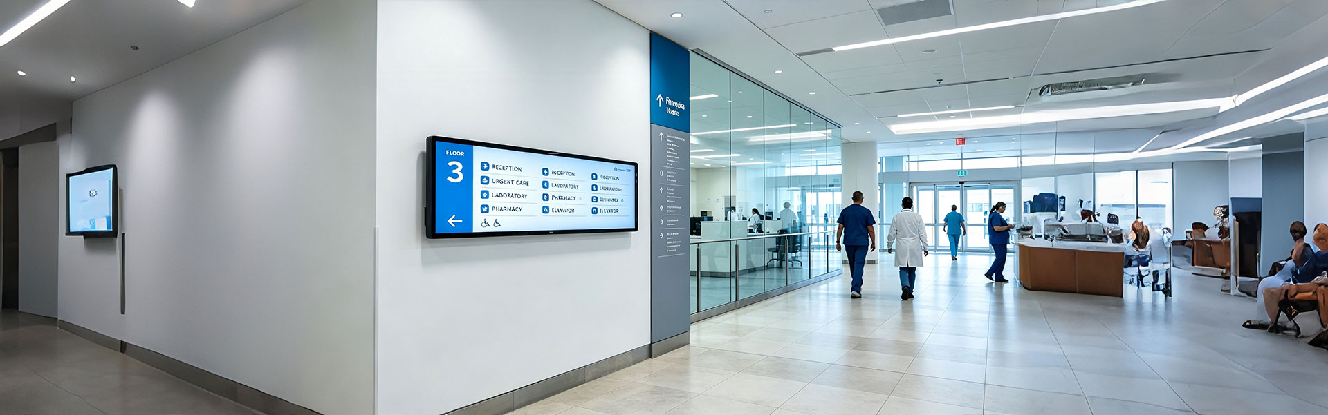
Floor Information Bar LCD Display Solution
Ultra-wide, high-brightness stretched bar LCD disp...
view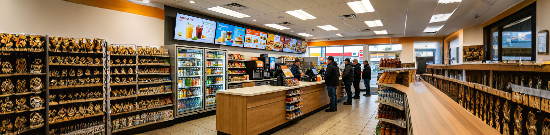
Convenience Store Bar LCD Display Solution
Ultra-slim, high-brightness stretched bar LCD disp...
view
Bus Passenger Information Stretched Bar Display Solution
A rugged, ultra-wide stretched bar display solutio...
viewRelated Products
You may also be interested in the following products