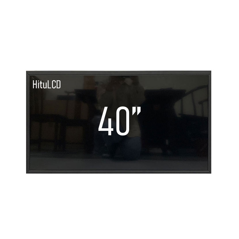
40 Inch 3000Nits Sunlight Readable Lcd Panel
MODEL: HT400FHD-D3000
Need customized solution?
Our engineering team is always ready to provide you with professional technical support and flexible customized services.
Understand light customization servicesBuilt by us. Configured for you.
HITULCD supplies LCD modules and display solutions directly from our manufacturing operation, giving OEMs, integrators and distributors direct access to engineering, customization and production.
Supply
Supplier Qualification
VerificationTechnical Specifications
| LCD PANEL PARAMETERS | HDMI/CONTROL BOARD SPECIFICATIONS | ||
|---|---|---|---|
| ITEM | DETAILS | ITEM | DETAILS |
| Description | HITULCD 40" QLED QUANTUM DOT HIGH COLOR GAMUT 350CD | Input Interface | HDMI, VGA,DP |
| Size | 40 | Power Input | AC 100~240V |
| Display area (mm) | 698.4(H)x 392.85(V) | OSD KEYS | 5 KEYS (POWER SWITCH, MENU, +, -, EXIT) |
| Resolution | 1920*1080 | OSD CONTROL | BRIGHTNESS, COLOR, CONTRAST, AUTO ROTATION, H/V POSITION, ETC. |
| Aspect ratio | 16:9 | ||
| Contrast ratio | 1200:1 | ||
| Pixel per inch (PPI) | 69 | ||
| Viewing angle | 178(H),178(V) | ||
| Display Colors | 16.7M, 72% NTSC | ||
| Response time(Typical) | 8ms | ||
| Signal Type | LVDS (2 ch, 8-bit) | ||
| Backlight | WLED, 30K hrs, With LED Driver | ||
| Power consumption | 50W | ||
| Dimensions (mm) | 718x412x14 | ||
| Mounting | VESA400x200 | ||
| Bezel size (U/B/L/R) | 7.9/7.9/7.9/7.9 | ||
| Operating temperature | 0℃~+50℃ | ||
| Storage temperature | -20℃~+60℃ | ||
| Weight (Net) | 5KG | ||
OEM/ODM Manufacturing Capability
HITULCD — Over a Decade of Industrial Display Manufacturing, Full-Process OEM/ODM Support
Audience: Overseas system integration engineers, procurement managers, project leads
Why Partner with HITULCD
When sourcing an OEM/ODM manufacturer overseas, the real question usually isn't "can they do it" — it's "does this factory actually have real production capacity and real process capability, or are they just a trading middleman relabeling someone else's output as OEM." HITULCD was founded in 2014 and has spent over a decade focused on one thing: industrial-grade high-brightness displays. We run our own COG/FOG bonding lines, automated cutting and assembly lines, and a full in-house reliability testing lab, with annual capacity of 120,000+ units and products exported to 38+ countries and regions. Whether you need a ready-made platform relabeled under your brand or a fully custom ODM build from scratch, we handle every step — design through mass production — inside our own factory, with no subcontracting layer in between.
What We Can Do for You
1. OEM Rebranding / Modification
If your product positioning is already defined and you just need your brand applied to a proven platform — or minor spec adjustments such as interface type, brightness tier, or housing color — we can move fast on our existing product lines without a from-scratch development cycle, shortening your sampling timeline.
2. Full-Spec ODM Development
If you have a unique structural requirement or application scenario — non-standard dimensions, a specific mounting method, custom optical parameters — our engineering team gets involved from the product-definition stage, providing integrated support across mechanical design, circuit design, and reliability test standards, built to your spec from the ground up.
Core Manufacturing Capabilities
⚙️ Core LCD Module Bonding Lines
Automated COG/FOG bonding lines (JYD-I900E fully-automatic bonder, JYD-F900E/F900A atomization bonding system) with micron-level alignment control, ensuring stable signal transmission and long module service life.
✂️ Custom Assembly and Structural Integration
From backlight modules to complete open-frame monitor assembly, our automated cutting, dispensing, and lamination lines (GH-1111 laser cutting machine, fully-automatic laminating and gluing production line) support both flexible customization and stable mass production.
🔬 Full-Process Reliability Testing and Quality Assurance
Every project goes through a complete quality-control workflow — dimensional inspection, environmental simulation, and aging testing — using 2D measuring instruments, high/low temperature test chambers, and microscope/visual inspection systems, to meet global industrial standards.
11-Step Traceable Manufacturing Process
Fully visualized precision workflow, from raw material input to final appearance inspection:
Cell Feeding
Vacuum Quenching
ACF Attachment
IC Alignment & Pre-Bonding
FOG Electrical Test
FPC Main Bonding
FPC Alignment & Pre-Bonding
IC Main Bonding
ITO Encapsulation
High-Temperature Adhesive & Label Attachment
Visual Inspection
Precision Production Equipment
| Equipment | Model | Function |
|---|---|---|
| Laser Cutting Machine | GH-1111 / 7.5KW | High-precision fiber laser cutting for smooth, burr-free panel edges — improving consistency and yield |
| OC Glass Cutting Machine | OC-1200A | Precision cutting of OC glass with accurate, stable dimensions, safeguarding bonding quality |
| Laser Marking Machine | LS-900Pro | High-stability laser technology for high-precision marking, cutting, and micro-processing |
| Automatic Mounter | PT-A12-B / 5.5KW | High-speed, high-precision surface mounting for stable component assembly |
| Temperature & Humidity Test Chamber | HYC-TH-80DH | Reliability testing under extreme environments to confirm industrial-grade durability |
| ACF Laminating Machine | F6-AS120 | High-precision conductive film lamination, ensuring 100% stable circuit connection |
Product Lines Available for Customization
5.5–27" industrial control display modules — for automation systems, HMI panels, embedded devices, industrial terminals
32–55" edge-lit LED backlighting kits (350–800 nits) — ideal for indoor digital signage
43–86" direct-lit backlighting kits (1000–1500 nits) — suited to semi-outdoor use
32–86" ultra-high-brightness kits (2000–3000 nits) — for sunlight-readable outdoor applications
Stretched bar displays — for shelves, transportation, elevators, retail spaces
Open-frame monitors — for kiosks, control systems, self-service equipment
Window / outdoor displays — for storefront windows and outdoor advertising
OLED / e-paper / touch integration solutions — for custom projects
Global Compliance and Certifications
Our commitment to quality and safety is backed by international certifications and rigorous testing standards:
CE (European Conformity, valid through Dec 2027)
FCC (Federal Communications Commission, valid through Dec 2027)
RoHS (Restriction of Hazardous Substances, valid through Dec 2027)
ISO 9001:2015
ISO 14001:2015
IATF 16949:2016
UL Certification
REACH Compliance
WEEE Directive
All products are tested in our own certified labs to confirm compliance with international safety and environmental standards.
Facilities and Production Environment
Our ISO 14644-1 certified cleanrooms, automated production lines, and strict quality-control processes work together to ensure the highest reliability, durability, and performance across our industrial display products. Modern office spaces and a dedicated engineering team support delivery for global clients — from concept to mass production, with a fully traceable and verifiable process at every stage.
Manufacturing Strength at a Glance
| Metric | Figure |
|---|---|
| Founded | 2014 |
| Export markets | 38+ countries and regions |
| Annual capacity | 120,000+ units (customizable specs) |
| Certifications | CE / FCC / RoHS / ISO9001 / ISO14001 / IATF16949 / UL / REACH / WEEE |
Next Step
Whether you need a fast rebranding solution on an existing platform or a full ODM build from your own drawings, reach out to our engineering team with your product positioning, target-market certification requirements, and expected order volume. We'll come back with a feasibility assessment, a preliminary cost range, and a development schedule.
Custom-Cut LCD Panel Service
Reference product: HT400FHD-D3000 (40" / 3000 nits / 1920×1080 direct-lit high-brightness panel)
Audience: Overseas system integration engineers, procurement managers, project leads
Why This Matters
A standard high-brightness panel like the 40" 3000-nit HT400FHD-D3000 rarely matches the exact cutout of a real enclosure. Fuel dispensers, in-vehicle consoles, custom advertising displays, and embedded instrument panels almost always need a panel trimmed to a non-standard size before it fits. The questions we hear most often are: how is the cut actually done, will the panel still work afterward, and how long until we can hold a sample. Below we walk through process feasibility, reliability assurance, and cost/yield/lead time — the three things that matter most when you're making a sourcing decision.
1. Process Feasibility Assessment
Which cutting method do you recommend?There are two main routes: mechanical wheel scribing (best for straight-line cuts, more tolerant of dimensional variance, lower cost, faster turnaround) and ultrafast laser cutting (better for irregular shapes, rounded corners, and narrow-bezel requirements, with lower edge stress but higher cost and longer lead time). Before quoting, we review your target dimensions and tolerance requirements — mechanical scribing is generally suitable down to roughly ±0.3mm, tighter tolerances or non-rectangular edges usually call for laser cutting — and recommend a process in writing rather than defaulting to one method.
Will the cut interfere with the circuit routing?This is the single biggest feasibility risk. The panel edge carries the Gate/Source driver traces and the COF/COG bonding area; if the cut line crosses into that region, the panel is unusable. To confirm feasibility before quoting, we typically need:
A drawing of the target outline dimensions, with tolerances marked
Any active-area (viewable image area) retention requirements
Mounting details — hole positions, chamfers, or other structural constraints, if applicable
Once we have this, we overlay the cut line against the original panel's trace layout to verify clearance from the TFT array and driver circuitry, and give you a clear go/no-go conclusion — or a suggested adjustment — before any quote is issued.
What's the edge-finishing standard after cutting?Cut edges are ground and chamfered to control edge flatness and remove micro-cracks introduced during scribing. This step matters because uncontrolled micro-cracks are exactly what propagates into a full fracture under drop or thermal-shock testing later.
2. Reliability and Edge-Sealing Assurance
How do you prevent leakage and moisture ingress at the cut edge?Cutting severs the panel's original frame-seal adhesive, leaving the cut cross-section exposed to liquid-crystal leakage and moisture intrusion. We apply a secondary sealing process to the cut edge — primarily UV dispensing, with epoxy resin sealing added on top for certain products depending on the cut location and exposure conditions — to rebuild a moisture and leak barrier along the exposed edge.
Can the cut module still pass reliability testing?Yes, but the baseline data needs to be evaluated separately — a cut panel has a different edge structure than the uncut original, so uncut-panel reliability data can't simply be carried over. For comparable past projects, we can typically share benchmark results from:
Dual 85 testing (85°C / 85% RH)
High-low temperature cycling
Thermal shock testing
Structural drop testing
We can target either consumer-grade or industrial-grade standards depending on your use case (outdoor, in-vehicle, industrial control cabinet, etc.), and we recommend locking in the test plan at the sampling stage — not after mass production — so there's no mismatch discovered later.
Any risk of light leakage or color shift at the cut edge?Edge Mura (light leakage, color shift) is the most commonly overlooked risk in cutting projects, and it usually comes from one of two causes: a gap between the sealed edge and the backlight module causing leakage, or the cut line sitting too close to the active area, where edge stress affects liquid crystal alignment. We run a lit-panel inspection at the sampling stage, checking brightness and chromaticity within roughly 1–2mm of the cut edge, and confirm it meets your acceptance criteria before moving to the next stage.
3. Cost, Yield, and Lead Time
What does it cost and how long to get a sample?NRE (engineering development) costs mainly cover cutting fixture/program development, trace-clearance simulation, edge-sealing process tuning, and first-article testing. The actual figure depends on cut complexity (straight vs. irregular), tolerance requirements, and whether a new fixture is needed — we issue a formal quote once we have your drawings. First-sample lead time (20pcs) is typically around 4–6 weeks, confirmed once the drawing is finalized.
What yield and MOQ should we expect at mass production?Yield on cutting programs depends mainly on cut-precision repeatability and edge-sealing consistency; established mechanical-cutting processes generally run noticeably higher yield than a newly developed irregular laser-cut program, so we'd recommend budgeting for a yield ramp-up period on a first mass-production run. MOQ for custom-cut or resized panels differs from our standard-product MOQ (as low as 1 unit for standard specs) and is confirmed in the quotation once the drawing and process are finalized — not adjusted after a deposit has been placed.
HT400FHD-D3000 Base Specifications (for drawing review reference)
| Item | Details |
|---|---|
| Model | HT400FHD-D3000 |
| Size | 40" |
| Brightness | 3000 nits |
| Resolution | 1920×1080 |
| Active display area | 698.4(H) × 392.85(V) mm |
| Contrast ratio | 1200:1 |
| Viewing angle | 178°(H) / 178°(V) |
| Backlight | WLED, direct-lit, 30,000 hrs rated life |
| Signal interface | LVDS (2ch, 8-bit) |
| Operating temperature | 0°C to +50°C |
| Storage temperature | -20°C to +60°C |
These are standard-product specs. Actual cut dimensions, trace-clearance margins, and active-area retention depend on the drawing review outcome for your specific project.
Next Step
If you already have a defined cut size and structural drawing, send us:
Target outline dimensions (with tolerances)
Mounting hole positions / structural constraints, if any
Use-case environment (indoor / outdoor / in-vehicle, etc.) so we can match the right reliability test standard
Our engineering team will respond with a written feasibility conclusion, a preliminary cost range, and a sampling schedule after reviewing your drawing.
Know The Terms Before You Inquire.
|
01 — Shipping Terms
Incoterms Available
EXW
Ex Works — pick up from our factory
FOB
Free On Board — most common for ocean freight
CIF
Cost, Insurance & Freight — to your port
|
02 — Order Minimum
MOQ: 1 Units
Applies to standard specs. Custom brightness, cutting or bezel may adjust MOQ, confirmed at quotation. Sample units available before bulk order
|
03 — Payment Protection
Multiple Secured Methods
|
A Real Factory. Publicly Verifiable.
|
Legal Company Name
Shenzhen Hantu Jiashi Technology Co., Ltd.
|
Unified Social Credit Code
91440300306068446B
|
|
Legal Representative
YUN CHEN
|
Registered Capital
RMB 2,000,000
|
|
Established
May 23, 2014 (11+ years operation)
|
Business Status
● Active / In Operation
|
|
Registered Factory Address
Building B, Gangshen Innovation Park, Huaning Road, Dalang Sub-district, Longhua District, Shenzhen, Guangdong, China
|
|
Contact HITULCD
We'll respond via email within 24 hours. If you'd like to discuss details over WhatsApp or a call, please leave a preferred time and contact method in your message — we will never call you unannounced.
Related solutions
This product is suitable for the following industry application scenarios
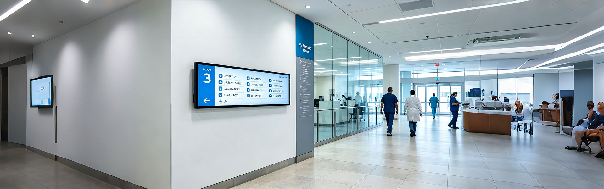
Floor Information Bar LCD Display Solution
Ultra-wide, high-brightness stretched bar LCD disp...
view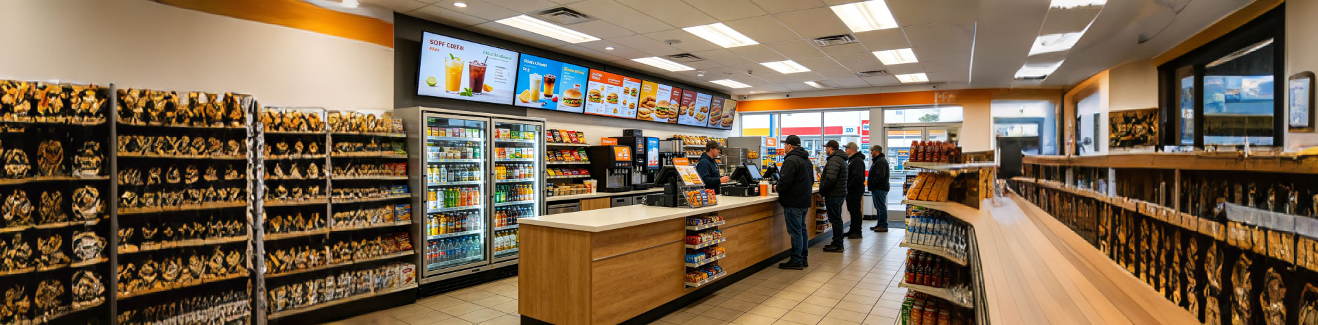
Convenience Store Bar LCD Display Solution
Ultra-slim, high-brightness stretched bar LCD disp...
view
Bus Passenger Information Stretched Bar Display Solution
A rugged, ultra-wide stretched bar display solutio...
viewRelated Products
You may also be interested in the following products
3000 Nits
40 Inch 3000Nits Sunlight Readable Lcd Panel
 3000 Nits
32 Inch Sunlight Readable LCD Panel For Outdoor Industrial OEM
 3000 Nits
43 Inch 3000nits Ultra High Brightness Direct-Lit LCD Display
