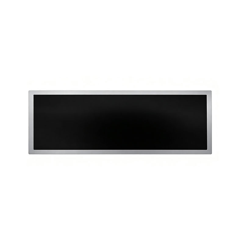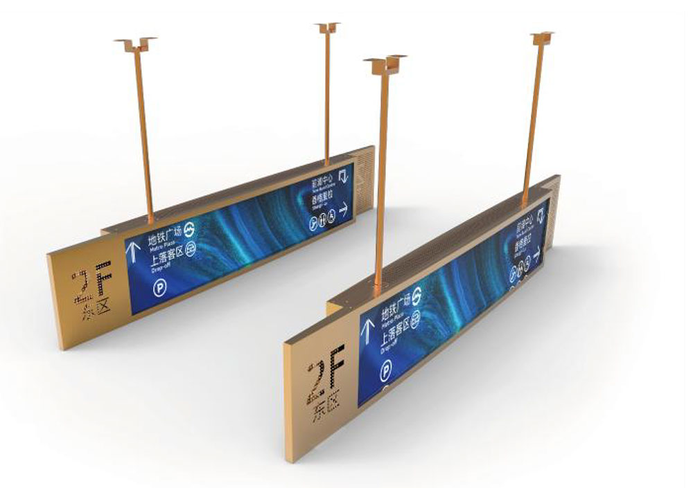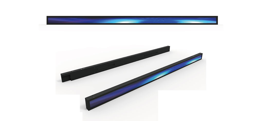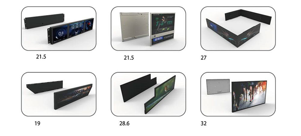
Ticket vending machines, fare gates, platform information boards, parking payment kiosks and self-service check-in desks share a design constraint that ordinary 16:9 panels handle badly: the enclosure is long, shallow and narrow. A standard panel forces the mechanical engineer to either waste front-face area on bezel and dead space, or redesign the housing around a display that was never intended for the application. Stretched (bar-type) LCD modules exist to solve that mismatch — and in ticketing and information terminals, they are increasingly the difference between a cabinet that looks deliberate and one that looks adapted.
This paper addresses the engineering substance behind custom stretched LCD modules: how the format is defined, what a high-brightness implementation actually requires, which environmental and electrical tests matter in public-terminal duty, and how a manufacturer should document evidence that each of those tests was performed on the units actually shipped.
1. What "Stretched" Means in Panel Terms
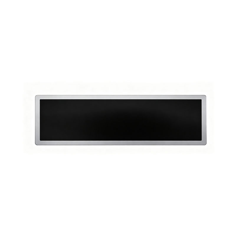
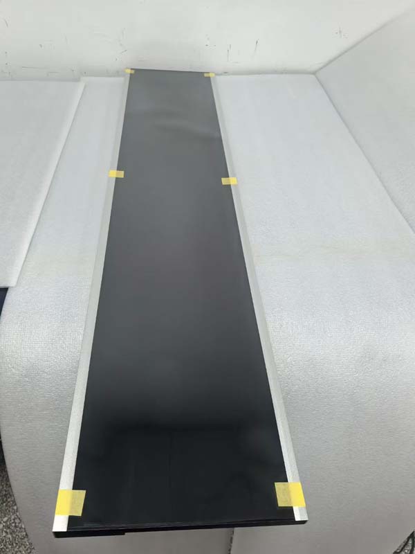
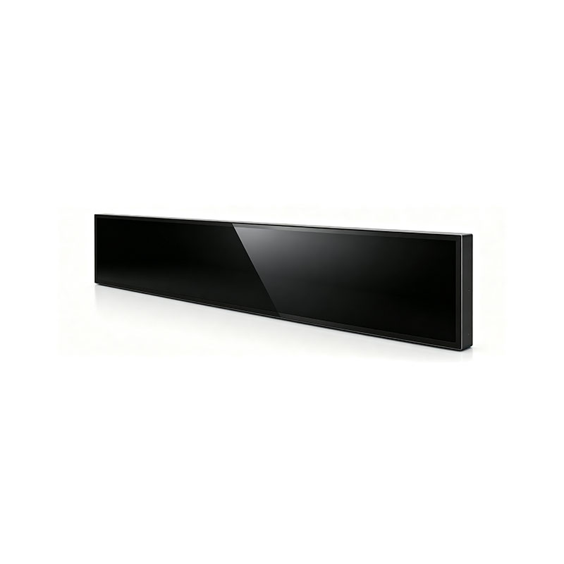
A stretched module is a liquid crystal display whose active area departs from the consumer aspect-ratio convention while keeping a diagonal that designers can specify. Typical ratios in terminal design include 16:3, 16:4, 21:9, 28:9, 37:9, and near-square variants such as 1:1 or 4:3 in small diagonals. The practical range for public-facing terminals sits between roughly 6.5 in and 47 in diagonal, with the most common ticket-machine sizes falling between 10 in and 29 in.
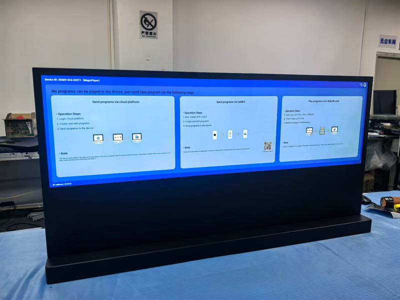
Three engineering realities follow from the format:
- Mother-glass economics. Stretched panels are cut from standard generation glass, so the ratio determines how many units fit per sheet. A ratio close to an existing cut pattern keeps tooling and yield viable; an exotic ratio may require dedicated masks, which is why custom formats usually carry a minimum order quantity and a longer first-article lead time.
- Backlight uniformity across the long axis. A 37:9 module at 1,200 nits is a difficult optical problem: the light path is long, the diffuser is under mechanical tension, and brightness falloff at the ends is where cheap designs fail. Direct-lit LED arrays with a well-designed light guide and a diffuser stack outperform edge-lit approaches at these ratios; edge-lit remains viable below roughly 16:4 and 600 nits.
- Mechanical stiffness. Long, thin modules flex. Frame stiffness, stiffener ribs behind the light guide, and controlled mounting-point spacing protect the cell from bending stress during transport, installation and thermal cycling.
2. High Brightness Is a System, Not a Number
Terminals are placed in railway concourses, atriums, roadside parking lots and uncovered platforms. Ambient illuminance on the front face can reach 50,000–100,000 lux in direct sun, and the display must remain legible while the enclosure may be sealed and fanless. Brightness alone does not deliver that.
2.1 Luminance and contrast budget
A 1,000-nit module with a 1,000:1 native contrast ratio produces a black level of about 1 nit. Under 60,000 lux of incident light, a front surface with 1.5% reflectance reflects roughly 290 nits — five hundred times the panel's own black level. The image survives only because the white state is bright and the reflected light is diffuse. The design levers are therefore: raise luminance (1,000–2,500 nits is the practical band for semi-outdoor; 700–1,000 nits for indoor concourses), reduce surface reflection with anti-reflective and anti-glare treatment, and raise contrast within the panel.
2.2 Optical bonding
Where a cover glass or capacitive touch sensor sits over the panel, air-gap lamination creates two extra reflections and traps a layer of air that fogs on cold mornings and traps dust over time. Full optical bonding with a cured index-matched adhesive removes those interfaces, improves contrast under sunlight by a factor of two to three in typical builds, increases impact resistance, and improves heat conduction from the front glass into the module's thermal path.
2.3 Thermal management in a sealed cabinet
Raising luminance raises LED heat. A 15-inch stretched module driven at 1,500 nits may dissipate 15–25 W in the backlight alone, inside an enclosure with no fan and a solar load on the front face. Practical countermeasures include:
- Aluminium-backed light guide with direct conduction to the rear chassis;
- LED binning and current derating curves that hold colour point over the operating temperature range;
- An NTC-thermistor-driven luminance foldback curve, so the module reduces brightness gracefully above a defined internal temperature rather than discolouring or failing;
- For cold-start requirements down to −30 °C, an integrated transparent heater on the cover glass with a thermostat, plus a warm-up delay before the host asserts the backlight enable line.
3. Electrical and Interface Customisation
Terminal integrators rarely want a bare panel with a flying lead. Customisation typically covers:
| Parameter | Common custom options | Design consequence |
|---|---|---|
| Interface | LVDS single/dual, eDP, MIPI DSI, parallel RGB | Matches existing SoC (Rockchip, i.MX, Intel Atom/Core, ARM SBC) without a bridge board |
| Connector & FPC | Position, orientation, length, locking type | Controls cable routing in shallow cabinets; must be fixed before tooling |
| Backlight drive | Constant-current board on module, PWM/analogue dimming, 0–100% linearity | Defines dimming curve for night-mode compliance in station environments |
| EDID / firmware | Custom timing set, gamma, colour temperature preset | Prevents plug-and-play mismatch on industrial motherboards |
| Mechanical | Mounting hole pattern, bezel width, front glass thickness, IK rating | Direct drop-in replacement for an existing cut-out |
| Shielding | Conductive gasket, ITO coating, grounded frame | EMC containment when the terminal has a certified radio module nearby |
One further point deserves emphasis: the module's timing set, dimming response and power-up sequence determine whether the terminal boots cleanly and whether the first frame is visible to a passenger within the required time. These are firmware-level deliverables, not catalogue attributes, and should be frozen together with the mechanical drawing.
4. Qualification: Which Tests Actually Matter
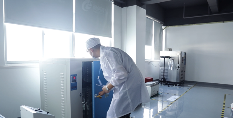
Public terminals face a specific stress profile: wide temperature range, high humidity, salt-laden air in coastal car parks, vandalism, continuous static content that causes image sticking, and 24/7 duty that consumes backlight lifetime. The following test set is representative of what a high-brightness stretched module should be qualified against.
| Test standard | Purpose | Typical severity |
|---|---|---|
| IEC 60068-2-1 (cold) / IEC 60068-2-2 (dry heat) | Operating and storage limits | −30 °C to +80 °C storage; −20 °C to +70 °C operating |
| IEC 60068-2-14 (thermal shock) | Bonding and seal integrity | −40 °C ↔ +85 °C, 50–100 cycles |
| IEC 60068-2-78 (damp heat, steady state) | Moisture ingress, condensation | +60 °C / 90% RH, 500–1,000 h |
| IEC 60068-2-52 (salt mist) | Coastal and roadside exposure | Severity 2, cyclic |
| IEC 60068-2-27 (shock) / IEC 60068-2-6 (vibration) | Transport and installation | 15 g / 11 ms; 10–500 Hz sweep |
| IEC 60529 (IP) | Front-face sealing | IP54 to IP65 at the gasket interface |
| IEC 62262 (IK) | Impact resistance of cover glass | IK07–IK10 depending on location |
| IEC 61000-4-2 (ESD) | Touch and bezel discharge | ±8 kV contact / ±15 kV air |
| EN 55032 / EN 55035 | Emissions and immunity for the assembled terminal | Class B where residential-adjacent |
| Optical measurement per VESA FPDM 2.0 | Luminance, uniformity, contrast, colour | 9-point uniformity ≥75%; ΔE ≤ 5 |
| MIL-STD-810 Method 505.5 (solar radiation) | Sunlight readability and heat load | Per project specification |
| Internal burn-in / image-sticking protocol | Static UI elements (fares, logos, QR frames) | 1,000 h static pattern, residual image ≤ specified delta |
Several of these deserve a note of interpretation. IP rating applies to the assembled terminal as installed, not to the bare module; a module can be sealed to the gasket plane and still leak once the customer's bezel is bolted on without controlled torque. ESD performance on a projected-capacitive stack depends heavily on the bonding layer thickness and the grounding of the cover glass, so it must be verified on the bonded assembly. And sunlight readability is a system property — it should be demonstrated with the final cover glass, coating and bonding stack, not inferred from bare-panel photometry.
5. Evidence Records: The Part Most Suppliers Skip
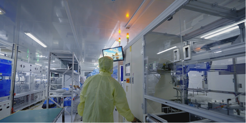
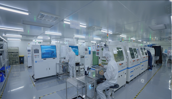
A test report proves that a test was run. An evidence record proves that the test was run on the configuration that was shipped. The distinction matters at audit, during a warranty dispute, and when a product is re-qualified after a component change. The governing principle is simple: every test standard has a corresponding evidence record, and every record is traceable to a serial number, a lot, a drawing revision and a golden sample.
A defensible record set contains, for each standard in the qualification plan:
- A traceability matrix row mapping requirement → test method → sample size → acceptance criterion → record identifier → responsible engineer.
- A serialised report naming the exact part number, hardware revision, firmware/binning version and glass coating specification of each unit tested.
- Calibration certificates for the instruments used (luminance meter, colourimeter, environmental chamber), valid at the test date.
- First-article inspection report and a retained golden sample, sealed and photographed, against which production units are compared at defined intervals.
- Batch records linking panel lot, LED bin, bonding lot and driver-board lot to the units that entered the field, so that a field failure can be traced back to a specific qualification campaign.
- Change-control log that triggers re-test when a material or process changes, with the specific standards re-run recorded.
When this structure is in place, a terminal manufacturer answering a tender question about environmental compliance can produce a record instead of a promise — and the design engineer can compare two supplier claims on equal footing.
6. Lifetime and Serviceability
Information terminals in stations often run 24 hours a day with a static layout. Two lifetime factors dominate: backlight lumen depreciation and image sticking. For a 1,500-nit module driven continuously, 50,000 to 70,000 hours to 50% luminance is a realistic target when the thermal design is competent; the same module in a poorly ventilated cabinet can lose a third of that. Ask for the derating curve, not the headline figure. For image sticking, specify the static pattern and the measurement of residual image after a defined recovery period, and consider a firmware-level pixel-shift or brightness-dither routine for UI areas that never change.
Serviceability is a customisation decision made early: a module with a replaceable backlight driver board and a defined connector access plane can be serviced in a public concourse in minutes, whereas a fully potted assembly may require returning the entire terminal.
7. Specification Checklist for Procurement
- Diagonal, active area, resolution and aspect ratio — with the cut-out dimensions that must be respected;
- Brightness at the final bonded stack, measured at 9 points, with the derating curve;
- Contrast, colour gamut, ΔE tolerance and viewing-angle behaviour along the long axis;
- Cover glass: thickness, AR/AG treatment, IK rating, print/black-print border;
- Touch: PCAP with glove and wet-finger operation, controller interface, ESD class;
- Operating and storage temperature, humidity, cold-start heater requirement;
- Interface, connector position, cable length, EDID and dimming curve;
- Mounting pattern, bezel dimensions, weight, rear clearance for the driver board;
- Qualification plan with the full evidence-record set listed per standard;
- Production test per unit (luminance, uniformity, pixel defects, hot-spot check) and the sampling plan for periodic re-verification.
Conclusion
A stretched LCD module is not a commodity panel with an unusual outline. It is a mechanical, optical, thermal and electrical compromise negotiated around a specific enclosure, a specific ambient light level and a specific service life. Getting it right requires that the brightness figure, the bonding stack, the thermal path, the interface firmware and the mechanical interface be specified together — and that the qualification evidence be recorded per standard against the shipped configuration. Terminals that meet those conditions stay legible in a sunlit car park in July and in an unheated platform in January, and they remain defensible in an audit years after the tender was won.
KEYWORDS: stretched LCD module, high brightness bar-type display, ticketing terminal LCD, custom LCD panel, sunlight readable display