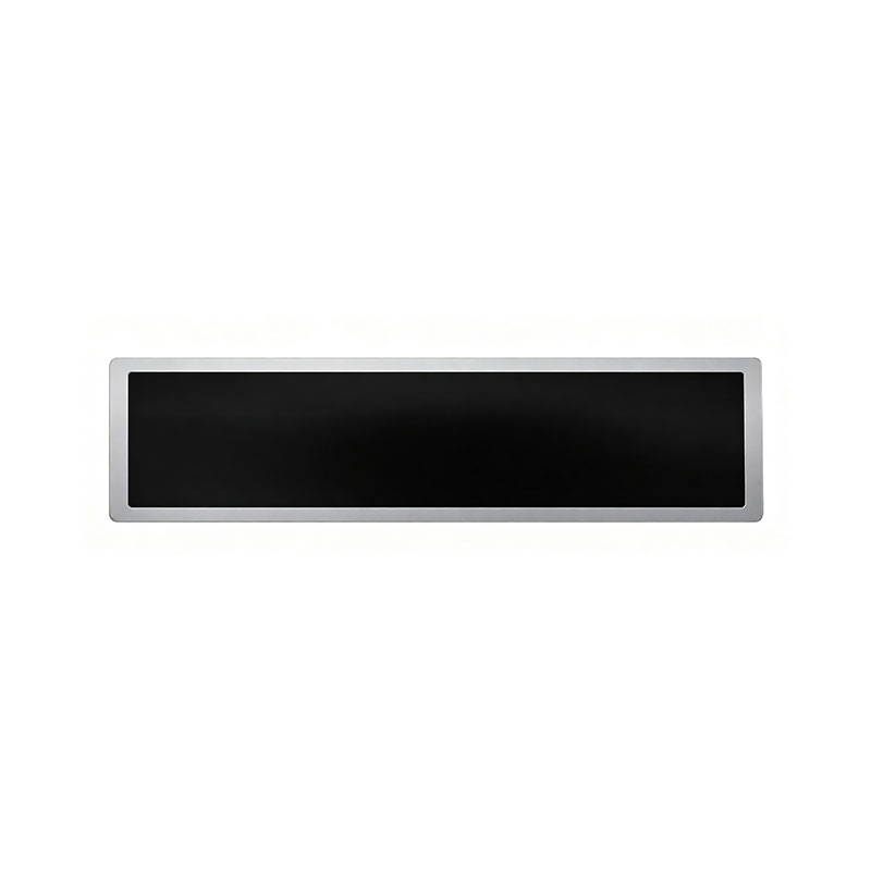
21.3 Inch Stretched Bar LCD Module LVDS EDP Interface
MODEL: HT213HBM
Need customized solution?
Our engineering team is always ready to provide you with professional technical support and flexible customized services.
Understand light customization servicesBuilt by us. Configured for you.
HITULCD supplies LCD modules and display solutions directly from our manufacturing operation, giving OEMs, integrators and distributors direct access to engineering, customization and production.
Supply
Supplier Qualification
VerificationTechnical Specifications
| LCD PANEL PARAMETERS | DRIVER BOARD SPECIFICATIONS | ||
|---|---|---|---|
| ITEM | DETAILS | ITEM | DETAILS |
| Model Number | HT213HBM | Input Interface | LVDS, 30 Pins |
| Brand | HITULCD | Signal Type | LVDS |
| Product Series | 23.8" Cut Panel Series | OSD KEYS | Depends on LVDS controller |
| Diagonal Size | 21.3" Cut Stretched Bar (Cut from 23.8" Panel, 1/3 Cut) | OSD CONTROL | Depends on LVDS controller |
| Resolution | 1920 × 360, Aspect Ratio 5.33:1 (>3:1) | ||
| Product Category | Graphic Type Display | ||
| Panel Type | a‑Si TFT‑LCD, Complete LCM Module | ||
| Physical Shape | Flat Rectangle | ||
| Display Area (A.A) | 531.36(W) × 99.63(H) mm | ||
| Overall Dimension | 561.36(W) × 129.63(H) mm | ||
| Max Thickness | 20 mm | ||
| LCD Technology | IPS, Transmissive Polarizer | ||
| Typical Brightness | 1000 NITS (Customizable: 300~1000 NITS) | ||
| Transmissive Contrast Ratio | Not specified | ||
| Viewing Angle | 89°/89°/89°/89°(Min.)(L/R/U/D) | ||
| Viewing Direction | Full Viewing Angle | ||
| Display Colors | 16.7M Colors | ||
| Backlight Type | WLED | ||
| Touch Panel | Without Touch Function | ||
| Application Fields | Digital Signage, Cut Stretched Bar Displays | ||
| Operating Temperature | 0 ~ 50 °C | ||
| Storage Temperature | -20 ~ 70 °C | ||
OEM/ODM Custom Cutting Solutions — Any Size Stretched Bar LCD
From standard panel to custom bar-format display — we engineer the exact aspect ratio and dimensions your project needs, at any size.
No Standard Size Fits Your Design? We Cut One That Does.
Off-the-shelf bar-type LCDs come in a handful of fixed sizes — 8.8", 12.3", 21.3", 27.6"... but real-world enclosures rarely match a catalog number. When your mounting space, mechanical housing, or product design calls for a display that doesn't exist as a standard SKU, our OEM/ODM cutting service converts standard TFT-LCD panels into any custom bar-format size and aspect ratio — from compact instrument strips to ultra-wide panoramic bars exceeding 30".
This is not a fixed product catalog. This is a manufacturing capability: tell us your target outline dimensions, resolution, and interface, and our engineering team will confirm feasibility against source panel availability and deliver a display built to your exact spec.
What We Offer
| Capability | Detail |
|---|---|
| Size range | Custom — from small instrument bars to large-format panoramic strips (project-dependent on source panel availability) |
| Aspect ratio | Fully custom — any stretched/bar ratio your enclosure requires |
| Source panels | Wide range of a-Si TFT-LCD panels from major panel makers, selected per your resolution/brightness/interface needs |
| Interface | LVDS, eDP — matched to your controller board |
| Touch integration | Optional PCAP touch + cover lens bonding |
| Driving board | Custom LVDS/eDP-to-HDMI/DP/USB-C driver board development available |
| Cutting method | Mechanical wheel scribing or ultrafast laser cutting, selected per tolerance and edge-quality requirement |
| Edge sealing | UV-cure adhesive sealing to prevent LC leakage and moisture ingress |
| MOQ | Flexible — scaled to prototype, pilot-run, and mass-production stages |
Why Buyers Choose Our OEM/ODM Cutting Service
One-stop feasibility to mass production.You don't need to source panels, negotiate with a glass fab, and manage a separate sealing/testing vendor. We handle DFM review, cutting, edge sealing, optical inspection, driving board matching, and reliability testing under one project.
Engineering-first quoting, not guesswork.Every custom size request goes through a technical DFM (Design for Manufacturing) review before we quote — checking whether your target dimensions avoid the source panel's Gate/Source trace and TFT array regions, confirming realistic tolerances, and flagging any design conflict early, before tooling cost is committed.
Built for demanding B2B applications.Our cutting and sealing process is developed for embedded, industrial, transportation, and kiosk applications — not consumer novelty displays. That means edge sealing, thermal cycling, humidity resistance, and drop testing are treated as standard qualification steps, not optional add-ons.
Scales with your program.Whether you need 20 units for a design validation build or a recurring mass-production supply, the same engineering process applies — we support prototype, pilot, and volume phases without re-engineering the design each time.
How the Custom Cutting Process Works
Share your requirement — target outline size, active area, resolution, interface, and application environment (or a mechanical drawing, if available).
DFM feasibility review — our team checks source panel compatibility, cut-line placement, and manufacturability, and confirms achievable tolerances.
Quotation & NRE proposal — pricing, sample lead time, and (if applicable) tooling/setup cost.
First article sampling — typically a small batch for dimensional, optical, and functional validation.
Reliability qualification — thermal cycling, humidity, and structural testing per your target grade.
Mass production — scaled to your MOQ and delivery schedule, with consistent process control across builds.
Typical Applications for Custom-Cut Bar Displays
Automotive center console and instrument cluster strips (non-standard vehicle platforms)
Elevator, lobby, and building directory information bars
Custom kiosk and vending machine housings
Retail shelf-edge and digital signage installations with fixed mounting constraints
Industrial control panels and equipment HMIs with legacy or non-standard cutouts
Transportation passenger information displays
Start Your Custom Cutting Project
Send us your target dimensions, resolution, and application details — or a mechanical drawing (DXF/DWG) if you have one — and our engineering team will return a feasibility assessment and quotation. No size is "off the menu"; if it can be cut from an available source panel, we'll tell you how.
Request a Feasibility Review / RFQ →
Note: Achievable size range, tolerance, and lead time depend on source panel availability and cut geometry, and are confirmed per project during DFM review.
21.3" Stretched Bar LCD Display Module — LVDS / eDP Interface
Ultra-wide format TFT-LCD module engineered for panoramic HMI, digital signage, transportation, and industrial control applications.
⚠️ Note on specifications: Several values below marked "(Ref.)" are industry-standard reference values for the 21.3" class of stretched-bar LCD modules and should be confirmed against your factory's actual datasheet/mechanical drawing before publishing or quoting to end customers.
Overview
The 21.3" Stretched Bar LCD Module is a custom aspect-ratio TFT-LCD display, converted from a standard-format panel through precision glass cutting and re-sealing. Its elongated, panoramic form factor is purpose-built for applications where a conventional 4:3 or 16:9 display cannot fit the available mounting space — such as vehicle center consoles, self-service kiosks, elevator information bars, and instrumentation dashboards.
This module supports both LVDS and eDP digital interfaces, allowing direct integration with a wide range of embedded SoCs, industrial PCs, and Android/Linux/Windows-based controller boards without an external HDMI-to-LVDS converter.
Key Specifications
| Parameter | Value |
|---|---|
| Panel size | 21.3" (diagonal) |
| Display technology | a-Si TFT-LCD, Normally Black |
| Aspect ratio | Ultra-wide stretched bar (Ref. — confirm exact ratio) |
| Resolution | Ref.: 1920 × 360 (confirm actual cut resolution) |
| Interface | LVDS (Ref.: 1ch/2ch, 6/8-bit) or eDP, per customer requirement |
| Brightness | Ref.: 500–1000 cd/m² (Typ.) |
| Contrast ratio | Ref.: 1000:1 (Typ.) |
| Viewing angle | Ref.: 170°/170° (H/V, CR ≥ 10) |
| Backlight | White LED, edge-lit |
| Operating temperature | Ref.: -20°C to +70°C (industrial grade available) |
| Storage temperature | Ref.: -30°C to +80°C |
| Touch option | Optional PCAP touch (cover glass bonding available) |
| Lifetime (backlight) | Ref.: ≥ 30,000 hrs @ 25°C |
| Power supply | 3.3V / 5V (Typ., per driving board) |
| Certification | RoHS compliant; REACH on request |
Core Features
Custom Stretched-Bar Format — Precision glass cutting from standard TFT panels to non-standard, ultra-wide dimensions tailored to your enclosure.
LVDS / eDP Native Support — Simplifies integration with embedded boards; no external scaler required for compatible controllers.
Wide Operating Temperature Range — Suitable for automotive, transportation, and outdoor kiosk environments.
Sealed Edge Treatment — Post-cut edge sealing process to protect against moisture ingress and liquid crystal leakage at the cut boundary.
Optional Touch Integration — PCAP touch panel and cover lens bonding available for interactive applications.
Custom Driving Board — LVDS/eDP-to-controller driver board can be co-designed for your specific timing and resolution.
Applications
Vehicle center console / instrument cluster bar displays
Elevator and building directory information bars
Self-service kiosks and vending machines
Digital signage and retail shelf-edge displays
Industrial control panel HMIs
Transportation (bus, rail) passenger information displays
Interface & Integration
| Item | Detail |
|---|---|
| Signal input | LVDS (single/dual channel) or eDP |
| Connector | Ref.: confirm pin-count and pitch with factory drawing |
| Compatible controller boards | Standard embedded SBCs supporting LVDS/eDP panel timing (Raspberry Pi CM, Rockchip, i.MX, x86 industrial boards, etc.) |
| Driving board | Available as an option — converts HDMI/DP/VGA to the panel's native LVDS/eDP timing |
Customization & OEM Capability
As a stretched-bar LCD specialist, we support full custom development from standard panel sourcing through to finished module:
Custom cutting size and aspect ratio per customer mechanical drawing
Resolution and active area confirmation via DFM (Design for Manufacturing) review
Custom FPC/cable length and connector type
Optional cover lens bonding (OCA/OCR) and anti-glare/AG or anti-fingerprint/AF coating
Custom driving board and firmware/EDID configuration
Ordering Information
| Item | Detail |
|---|---|
| Sample lead time | Ref.: 15–20 working days after drawing confirmation (project-dependent) |
| Sample quantity | Ref.: 20 pcs typical for first article |
| MOQ (mass production) | Ref.: to be confirmed based on cutting size and panel source availability |
| Payment terms | T/T, L/C — negotiable per order volume |
| Warranty | 12 months standard |
Request a formal quotation and datasheet through our RFQ form — mechanical drawings (DXF/DWG) and resolution/timing requirements are welcome for a fast feasibility review.
Technical FAQ — Engineering & Procurement Reference
For overseas engineers, procurement managers, and project owners evaluating custom-cut stretched-bar LCD feasibility.
1. Cutting Process & Feasibility
What cutting method do you recommend, and what tolerances apply?Two main methods are used for panel-to-bar conversion: mechanical wheel scribing (cutting wheel/scribe-and-break) and ultrafast laser cutting (picosecond/femtosecond laser). Mechanical scribing is more cost-effective for straight-line cuts on non-critical edges; laser cutting offers tighter tolerance control and lower micro-crack risk, and is recommended when the cut line passes close to active circuitry or when a smoother, chip-free edge is required. Standard dimensional tolerance is typically ±0.2–0.3 mm, refined to ±0.1 mm with laser cutting — final tolerance is confirmed per project after DFM review.
Will the cut line interfere with the panel's Gate/Source traces or TFT array area?This depends entirely on where the new cut boundary falls relative to the original panel's active area and driver IC/COF bonding region. Before quoting feasibility, we require:
The target outline dimensions and desired active area (with tolerance)
The source panel's original datasheet (active area, Gate/Source driver location, COF/TAB bonding position)
Any keep-out zone requirements from your enclosure design
Our engineering team performs a DFM check against the source panel's internal layout to confirm the cut line avoids active circuitry, and will flag any conflict before sample production begins.
What edge quality standard applies after cutting?Post-cut edges are inspected for flatness and chip/micro-crack control under standard optical inspection. Typical acceptance criteria limit visible chipping to a defined edge-band width (e.g., ≤0.1–0.2 mm from the glass edge) with no crack propagation toward the active area — exact AQL/inspection criteria are documented in the project's quality agreement.
2. Reliability & Edge Sealing Assurance
How do you prevent liquid crystal leakage and moisture ingress at the cut edge?Cut edges undergo a secondary sealing process, typically UV-cure adhesive dispensing along the exposed glass edge, forming a barrier against LC leakage and moisture penetration. Depending on the application environment, additional edge coating or a secondary structural adhesive bead may be applied for enhanced protection.
Can the cut module pass standard reliability testing, and can you share benchmark data?Cut/sealed modules are validated against consumer- or industrial-grade reliability standards depending on end-use (please specify your target grade for us to align test scope). Typical test items referenced for similar cutting projects include:
Double 85 (85°C/85%RH) high-temperature high-humidity test — typically 96–240 hrs depending on grade
Thermal shock / cold-hot cycling — typically -20°C to +60°C or -30°C to +70°C, multiple cycles
Structural drop test — per customer's mechanical enclosure spec
Specific pass/fail benchmark data from prior cutting projects can be shared under NDA upon request, as results vary by panel source, cut geometry, and sealing process revision.
Does edge sealing create light leakage or color shift (Mura) near the cut boundary?A well-controlled cutting and sealing process should not introduce visible light leakage or Mura at the edge under normal viewing conditions. Risk increases if the cut line is too close to the backlight edge or if edge sealing is inconsistent — our process includes optical inspection (light leakage and Mura check) as a standard QC gate before shipment.
3. Cost, Yield & Lead Time
What is the NRE cost and first-sample lead time for a custom cutting project?NRE (cutting tool/fixture setup, DFM engineering, first-article validation) is quoted per project based on cut complexity and source panel. As a general reference, first-sample turnaround (e.g., 20 pcs) typically runs 15–20 working days after drawing and specification confirmation — final quotation and lead time are provided after feasibility review.
What yield and MOQ should we expect at mass production?Mass-production yield for cutting projects typically ranges in the 90%+ range once the process is qualified and stable, though this varies with cut geometry complexity and source panel consistency. MOQ is generally driven by source panel MOQ and cutting batch efficiency — please share your target volume so we can confirm the most cost-effective MOQ tier.
This content is provided as a general engineering reference. Exact tolerances, test standards, and commercial terms should be confirmed in a formal quotation and quality agreement specific to your project.
Know The Terms Before You Inquire.
|
01 — Shipping Terms
Incoterms Available
EXW
Ex Works — pick up from our factory
FOB
Free On Board — most common for ocean freight
CIF
Cost, Insurance & Freight — to your port
|
02 — Order Minimum
MOQ: 1 Units
Applies to standard specs. Custom brightness, cutting or bezel may adjust MOQ, confirmed at quotation. Sample units available before bulk order
|
03 — Payment Protection
Multiple Secured Methods
|
A Real Factory. Publicly Verifiable.
|
Legal Company Name
Shenzhen Hantu Jiashi Technology Co., Ltd.
|
Unified Social Credit Code
91440300306068446B
|
|
Legal Representative
YUN CHEN
|
Registered Capital
RMB 2,000,000
|
|
Established
May 23, 2014 (11+ years operation)
|
Business Status
● Active / In Operation
|
|
Registered Factory Address
Building B, Gangshen Innovation Park, Huaning Road, Dalang Sub-district, Longhua District, Shenzhen, Guangdong, China
|
|
Contact HITULCD
We'll respond via email within 24 hours. If you'd like to discuss details over WhatsApp or a call, please leave a preferred time and contact method in your message — we will never call you unannounced.
Related solutions
This product is suitable for the following industry application scenarios
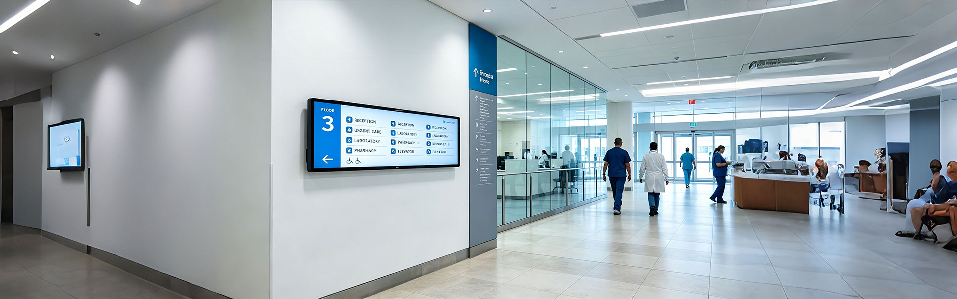
Floor Information Bar LCD Display Solution
Ultra-wide, high-brightness stretched bar LCD disp...
view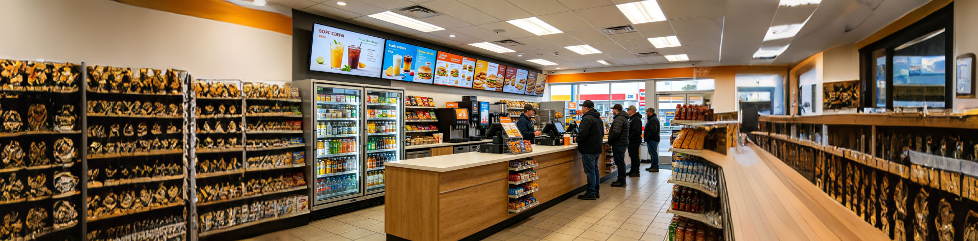
Convenience Store Bar LCD Display Solution
Ultra-slim, high-brightness stretched bar LCD disp...
view
Bus Passenger Information Stretched Bar Display Solution
A rugged, ultra-wide stretched bar display solutio...
viewRelated Products
You may also be interested in the following products