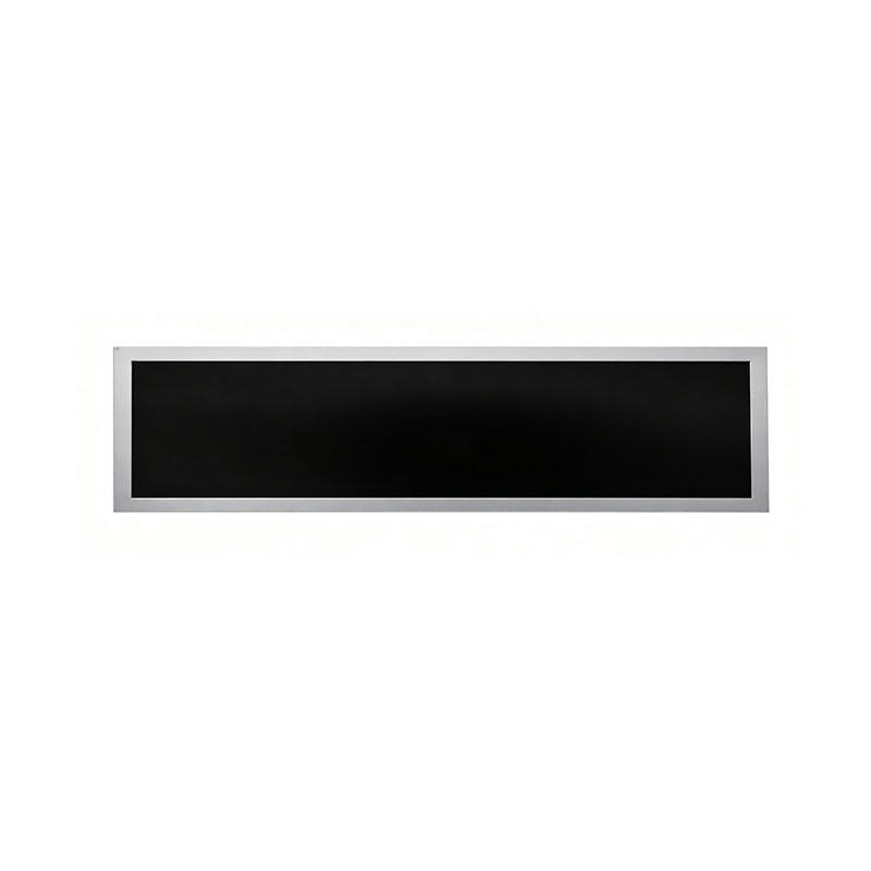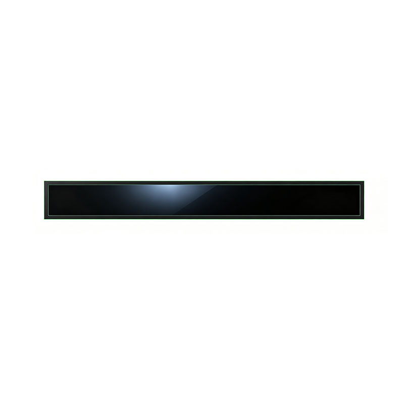
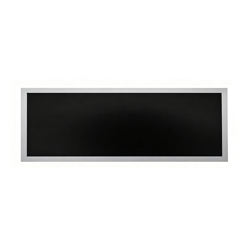
19.1 Inch Strip Form TFT LCD Module
MODEL: HT191HBM
Need customized solution?
Our engineering team is always ready to provide you with professional technical support and flexible customized services.
Understand light customization servicesBuilt by us. Configured for you.
HITULCD supplies LCD modules and display solutions directly from our manufacturing operation, giving OEMs, integrators and distributors direct access to engineering, customization and production.
Supply
Supplier Qualification
VerificationTechnical Specifications
| LCD PANEL PARAMETERS | DRIVER BOARD SPECIFICATIONS | ||
|---|---|---|---|
| ITEM | DETAILS | ITEM | DETAILS |
| Model Number | HT191HBM | Input Interface | LVDS, 30 Pins |
| Brand | HITULCD | Signal Type | LVDS |
| Product Series | 21.5" Cut Panel Series | OSD KEYS | Depends on LVDS controller |
| Diagonal Size | 19.1" Cut Stretched Bar (Cut from 21.5" Panel, 1/3 Cut) | OSD CONTROL | Depends on LVDS controller |
| Resolution | 1920 × 360, Aspect Ratio 5.33:1 (>3:1) | ||
| Product Category | Graphic Type Display | ||
| Panel Type | a‑Si TFT‑LCD, Complete LCM Module | ||
| Physical Shape | Flat Rectangle | ||
| Display Area (A.A) | 476.64(W) × 89.37(H) mm | ||
| Overall Dimension | 506.64(W) × 119.37(H) mm | ||
| Max Thickness | 20 mm | ||
| LCD Technology | IPS, Transmissive Polarizer | ||
| Typical Brightness | 1000 NITS (Customizable: 300~1000 NITS) | ||
| Transmissive Contrast Ratio | Not specified | ||
| Viewing Angle | 89°/89°/89°/89°(Min.)(L/R/U/D) | ||
| Viewing Direction | Full Viewing Angle | ||
| Display Colors | 16.7M Colors | ||
| Backlight Type | WLED | ||
| Touch Panel | Without Touch Function | ||
| Application Fields | Digital Signage, Cut Stretched Bar Displays | ||
| Operating Temperature | 0 ~ 50 °C | ||
| Storage Temperature | -20 ~ 70 °C | ||
OEM / ODM Custom LCD Cutting Services
Any Size. Any Aspect Ratio. Any Shape — Engineered from Standard TFT Glass into Displays That Fit Your Product
Your product is not 16:9. Your display shouldn't be either.We cut, seal, re-polarize and re-assemble TFT LCD panels to your exact outline — from ultra-wide bar displays to round and shaped screens — with engineering support from feasibility to mass production.
Send Your Drawing for a Free Feasibility Review · Request Samples (from 20 pcs)
Why Custom-Cut Displays?
Standard displays follow the consumer TV and monitor market: 16:9, 16:10, 4:3. But real products don't. Engineers designing shelf rails, elevator headers, vehicle dashboards, vending machines, control consoles and architectural signage face the same problem: the display available is not the display required.
Custom cutting solves that without the cost and lead time of a new-glass fab program.
| Challenge | Standard panel | Custom-cut display |
|---|---|---|
| Enclosure has a narrow aperture | Wasted space, oversized bezel | Panel matches the opening |
| Need a long strip (5:1 – 32:1) | Not available off the shelf | Cut to length, full-HD-width sharpness |
| Need a round, notched or L-shaped screen | Not possible | Laser-cut shaped outlines |
| Low-to-mid volume, high mix | New-glass tooling is uneconomical | Low NRE, samples from 20 pcs |
| Supply risk on niche panels | Single-source, long lead times | Built on mainstream, high-volume base panels |
Market Drivers We See From OEM Customers in Europe and North America
Retail digitalization — shelf-edge price and promo strips, dynamic pricing, in-store media networks.
Public transport and smart mobility — passenger-information strips, in-vehicle displays, station tickers.
Compact, space-constrained equipment — vending, kiosks, EV chargers, gaming terminals, elevators.
Industrial HMI and instrumentation — narrow status bars, dashboards, panel-mount displays with unusual apertures.
Product differentiation — brands want distinctive display shapes and proportions, not the same rectangle as competitors.
Supply-chain resilience — buyers want alternatives to single-source niche panels and shorter development cycles.
What We Can Cut
Format Range
| Category | Capability |
|---|---|
| Stretched bar / strip | Aspect ratios from 5:1 up to 32:1, sizes from 8" to 88" (project dependent) |
| Custom rectangle | Any length/width within the base panel's usable area |
| Shaped displays | Round, semi-round, notched, L-shaped, trapezoid, rounded corners (laser cutting) |
| Portrait / landscape | Either orientation supported |
| Size range | Small/medium modules to large-format panels (18.5" – 55"+ typical for bar formats) |
Cutting Technologies
| Method | Best for | Typical tolerance* |
|---|---|---|
| Mechanical scribe-and-break (diamond wheel) | Straight cuts, rectangular and bar formats, cost-efficient volume | ±0.1 mm |
| Ultra-fast (picosecond) laser cutting | Shaped outlines, tight tolerances, narrow borders, internal cutouts | ±0.05 mm |
*Typical values. Final tolerance is defined per project after feasibility review.
Our OEM / ODM Service Model
OEM — Build to Your Specification
You provide the drawing and requirements; we manufacture to your spec.
Cutting and assembly to your outline, resolution, brightness and interface
Your branding, labeling and packaging
Customer-approved specification and change-control
Stable supply and lifecycle management
ODM — We Design It With You
You describe the application; our engineers design the solution.
Base-panel selection and cut-layout design
Backlight, mechanical and thermal design
Driver-board / controller integration
Touch, optical bonding and cover-glass selection
Complete display module or subsystem ready for integration
Full Customization Menu
| Area | Options |
|---|---|
| Outline | Custom size, ratio, shape, corner radius |
| Brightness | 300 / 500 / 800 / up to 1,000 nits |
| Backlight | Edge-lit or direct-lit, custom LED layout, low-profile designs |
| Touch | PCAP with glove / water-rejection tuning |
| Bonding | Air-gap or optical bonding (OCA / OCR) |
| Cover glass | AG / AR / AF coatings, chemically strengthened, printed borders |
| Interface | LVDS, eDP, MIPI DSI, HDMI, DP |
| Driver board | Standard controller, custom PCB, or Android/Linux media-player |
| Environment | Commercial or wide-temperature (−20 °C to +70 °C) |
| Mechanical | Open frame, metal chassis, custom brackets and mounting |
| Branding | Logo, labeling, packaging, documentation |
Our Process — From Drawing to Volume
| Step | What happens | Typical timing* |
|---|---|---|
| 1. Requirement review | You share drawing, application, environment and volume | Day 0 |
| 2. Feasibility study | Cut-line overlay on the base panel; check gate/source routing, TFT array, seal line, driver location; recommend cutting method | 3–5 working days |
| 3. Proposal & quotation | Outline drawing, spec, NRE, unit price, MOQ, lead time | 2–3 working days |
| 4. Engineering samples | 20 pcs built on the qualified process | 3–4 weeks |
| 5. Validation | Optical, electrical and reliability testing; your evaluation and sign-off | 2–4 weeks |
| 6. Pilot run | Process lock, yield confirmation, AQL agreement | 2–3 weeks |
| 7. Mass production | Volume supply with traceability and lifecycle management | 6–8 weeks per order |
*Typical timings; actual schedule depends on base-panel availability and project complexity.
What We Need From You to Start
Outline drawing (DXF / DWG / STEP / PDF) or a description of the target enclosure
Target resolution, active area and viewing direction
Brightness, interface and touch requirements
Operating environment and reliability class
Estimated annual volume and target SOP date
Built for Reliability: Engineering the Cut Edge
Cutting is not the hard part — making the cut edge last is. Our process is built around four control points:
1. Layout Feasibility
Before any glass is cut, we overlay your outline on the original panel design to protect the TFT array, gate/source fan-out, shorting bars and seal line. You receive a written verdict: Go / Go with modification / No-go, with reasoning.
2. Edge Quality
| Item | Control (typical) |
|---|---|
| Chipping | ≤ 0.1 mm, none extending into the seal or active area |
| Micro-cracks | Microscope inspection of cut edges; none propagating toward active area |
| Verticality | 90° ± 1° |
| Finishing | Fine polish / chamfer on request |
3. Edge Sealing
Automated precision dispensing of UV-curable, low-moisture-permeability sealant along the cut edge
Thermal post-cure and optional secondary moisture barrier
Automated optical inspection for voids and gaps
Lot-based leak and moisture checks
4. Optical Integrity
Polarizer re-alignment to the new boundary
Edge light-shielding to prevent leakage
100% inspection at multiple gray levels for edge Mura, light leakage and color shift in first-article and volume production
Reliability Program (adapted per project)
| Test | Typical condition |
|---|---|
| High-temp / low-temp operation | Per grade, 500 h |
| High-temp / high-humidity | 60 °C / 90% RH, 500 h; 85 °C / 85% RH on request |
| Thermal shock | −30 °C ↔ +80 °C, 100 cycles |
| Vibration | IEC 60068-2-64 or customer profile |
| Shock / drop | IEC 60068-2-27; ISTA 2A packaged drop |
| ESD | IEC 61000-4-2, ±8 kV contact / ±15 kV air |
Environmental test data from comparable cut-panel projects are available under NDA.
Commercial Terms at a Glance
| Item | Information |
|---|---|
| Engineering samples | From 20 pcs |
| NRE | Project-dependent, quoted after feasibility review; may be credited against volume orders |
| Mass-production MOQ | Typically from 500 pcs per order (lower for stocked standard cuts) |
| Sample lead time | Approx. 3–4 weeks |
| Volume lead time | Approx. 6–8 weeks |
| Expected yield | ≥ 95% in stable mass production (confirmed in pilot run) |
| Warranty | 12–24 months, per grade and application |
| Incoterms | EXW / FOB Shenzhen; CIF / DDP on request |
| Payment | T/T (30% deposit, 70% before shipment) or L/C at sight |
| IP & confidentiality | NDA before drawing exchange; your design remains your property |
Quality & Compliance
ISO 9001 quality management system
RoHS / REACH compliant materials; CE / FCC for finished-module configurations
100% electrical and optical final inspection with serial-number traceability
Outgoing inspection to ANSI/ASQ Z1.4 or customer-specific AQL
Pixel-defect criteria per ISO 9241-302 unless otherwise agreed
Last-time-buy notification and alternative-panel qualification for lifecycle continuity
Where Our Custom-Cut Displays Are Used
| Industry | Example applications |
|---|---|
| Retail | Shelf-edge strips, gondola signage, dynamic pricing, promotional banners |
| Transportation | Bus / tram / train passenger-information, station tickers, ceiling strips |
| Vertical transport | Elevator headers and car panels |
| Vending & kiosks | Top-mounted attract displays, status strips |
| Gaming & entertainment | Jackpot banners, cabinet marquee displays |
| Industrial & instrumentation | Control-panel bars, dashboards, test-equipment displays |
| Architecture & signage | Recess-fit strips, window-facing and outdoor-readable displays |
FAQ
Can you cut any panel, or only specific models?We select the base panel with the best cut layout for your outline. Not every panel can be cut to every size — that's why we run a feasibility review before quoting.
Laser or mechanical cutting — which is better?Mechanical scribing is efficient for straight cuts and bar formats. Laser cutting is chosen for shapes, tight tolerances and narrow borders. We recommend the method based on your drawing.
Will cutting affect reliability?When done with the right layout, sealing and inspection, cut displays can meet commercial and industrial reliability targets. Each new design goes through a validation plan agreed with you.
How small can the order be?Engineering samples from 20 pcs. Volume MOQ is discussed per project.
Can you add touch, optical bonding or a controller board?Yes — from bare module to complete display subsystem.
Do you support long-term programs?Yes: forecast-based supply plans, LTAs, buffer stock and last-time-buy management.
Is my design confidential?Yes. We sign an NDA before receiving any drawings.
Start Your Project
Send us your outline drawing, target specification and estimated volume. Within 2 working days you receive a first response, and a full feasibility report within 3–5 working days.
📧 Email: sales@[your-domain].com 🌐 Website: www.hitulcd.com
Free feasibility review · Samples from 20 pcs · NDA available
Capabilities and specifications shown are typical values and may be updated without notice. Final performance is defined in the customer-approved specification for each project.
19.1" Stretched Bar TFT LCD Module — 1920 × 360, 16:3 Ultra-Wide, Cut from Full-Size FHD Glass
Custom-cut ultra-wide TFT LCD for shelf-edge, transit, kiosk, vending and industrial HMI designs — engineered, sealed and tested for volume OEM/ODM programs.
| Form factor | Stretched bar / strip display, 16:3 aspect ratio |
| Resolution | 1920 (H) × 360 (V) |
| Brightness options | 500 nits standard · up to 1,000 nits high-brightness |
| Sample MOQ | 20 pcs (engineering samples) |
| Compliance | CE · FCC · RoHS · REACH (declarations available on request) |
Request Datasheet & Free Sample · Ask an Application Engineer
Overview
The 19.1-inch stretched bar TFT LCD module gives you a full-HD-width (1920 px) display in a strip only ~89 mm tall. It is produced by precision-cutting a standard 21.5" FHD TFT cell down to a 1920 × 360 active area, then re-sealing, re-polarizing and re-assembling it with a matching backlight and driver board.
Compared with a conventional 16:9 panel, a bar display lets you:
Fit into narrow apertures — shelf rails, elevator headers, bus/train ceiling strips, vending-machine top banners, control-panel bezels.
Show more information per millimeter of height — scrolling tickers, price and promo strips, status bars, dashboards, multi-zone layouts.
Keep full-HD sharpness — 1920 px horizontal resolution keeps text and graphics crisp even at close viewing distance.
Use proven, widely supported base glass — the cut design inherits the supply-chain stability and interface ecosystem of mainstream 21.5" FHD panels.
Typical Applications
| Segment | Typical use |
|---|---|
| Retail | Shelf-edge displays, gondola strips, ESL-style dynamic pricing, promo banners |
| Public transport | Bus/train/metro interior passenger-information strips, station platform tickers |
| Vertical transport | Elevator car headers, lobby information strips |
| Vending & gaming | Top-mounted attract screens, jackpot banners, status strips |
| Industrial & HMI | Machine control strips, dashboards, test-equipment status bars |
| Digital signage | Architectural recesses, window-facing signage, menu boards |
Key Specifications
Values below are standard reference specifications. Final figures are confirmed in the customer-approved datasheet for each project.
Display
| Parameter | Specification |
|---|---|
| Diagonal size | 19.1" (485 mm) |
| Aspect ratio | 16:3 |
| Resolution | 1920 × 360 pixels |
| Active area (W × H) | 476.6 × 89.4 mm (typ.) |
| Pixel pitch | 0.248 × 0.248 mm |
| Panel type | a-Si TFT, transmissive, normally black |
| Technology | IPS / ADS wide-angle (configurable) |
| Viewing angle | 178° / 178° (H/V, CR ≥ 10) |
| Color depth | 16.7M colors (8-bit), 72% NTSC (typ.) |
| Contrast ratio | 1000:1 (typ.) |
| Response time | 25 ms (typ.) |
| Refresh rate | 60 Hz |
Optical & Backlight
| Parameter | Specification |
|---|---|
| Brightness | 500 cd/m² (typ.) standard; 800–1,000 cd/m² high-brightness option |
| Backlight | White LED, edge-lit (standard) / direct-lit (high-brightness) |
| Backlight lifetime | ≥ 50,000 hours (typ., at 25 °C, to 50% initial brightness) |
| Brightness uniformity | ≥ 80% (9-point) |
| Dimming | PWM, 100% – 5% (customizable) |
Electrical & Interface
| Parameter | Specification |
|---|---|
| Panel interface | LVDS (dual channel, 8-bit), 30-pin (typ.) |
| Optional driver board | HDMI / DP / VGA input · eDP · MIPI · Android/Linux media player boards on request |
| Logic supply | 3.3 V (typ.) |
| Backlight supply | 12 V DC (typ.) / 24 V DC on request |
| Power consumption | Approx. 12–18 W (standard brightness, typ.) |
Environmental
| Parameter | Standard grade | Wide-temperature grade (option) |
|---|---|---|
| Operating temperature | 0 °C to +50 °C | −20 °C to +70 °C |
| Storage temperature | −20 °C to +60 °C | −30 °C to +80 °C |
| Operating humidity | 10–90% RH, non-condensing | 10–90% RH, non-condensing |
| Duty cycle | 24/7 | 24/7 |
Mechanical (customizable)
| Parameter | Specification |
|---|---|
| Module outline | Customized per enclosure (typical thickness 8–12 mm bare module) |
| Bezel / frame | Open-frame, metal chassis, or narrow-bezel options |
| Mounting | Screw-hole brackets, side-mount, VESA-style, custom |
| Weight | Approx. 1.0–1.5 kg (open-frame, typ.) |
Customization Options
| Option | Choices |
|---|---|
| Size & aspect ratio | 18.5" – 55" range; 5:1 to 32:1 ratios; custom cut lengths |
| Brightness | 300 / 500 / 800 / 1,000 nits |
| Touch | Projected capacitive (PCAP), optional glove/water-rejection tuning |
| Bonding | Air-gap, or optical bonding (OCA / OCR) for sunlight readability and anti-fog |
| Cover glass | Anti-glare (AG), anti-reflective (AR), anti-fingerprint (AF), chemically strengthened |
| Interface | LVDS, eDP, MIPI DSI, HDMI, DP |
| Temperature | Commercial or wide-temperature (−20 °C to +70 °C) |
| Controller | Bare panel, driver board, or full Android/Linux media-player solution |
| Branding | Custom logo, FPC/connector position, silk-screen, packaging |
Engineering & Manufacturing Process
We know that a cut-glass display is a process-critical product. The sections below answer the questions that design engineers and quality teams ask most often.
1. Cutting Method & Dimensional Tolerance
| Item | Approach |
|---|---|
| Cutting technology | Mechanical scribing (diamond wheel) for straight cuts on standard bar formats; ultra-fast (picosecond) laser cutting for tight tolerances, narrow borders, or shaped (non-rectangular) outlines |
| Typical dimensional tolerance | ±0.1 mm (mechanical) · ±0.05 mm (laser) — tighter values reviewed case by case |
| Selection criteria | Determined per project during feasibility review, based on cut position, remaining border width, glass thickness and target edge quality |
2. Layout Feasibility — Gate/Source Routing & TFT Array Avoidance
Before any glass is cut, our engineers overlay your target outline onto the original panel's cell design to make sure the cut line does not touch the TFT array, gate/source fan-out, shorting bars, or seal line.
To start a feasibility review, please provide:
Target outline drawing (DXF / DWG / STEP / PDF)
Target resolution, active area and viewing direction
Preferred base panel (or let us recommend one from our qualified list)
Interface, connector and FPC position requirements
Touch, bonding or cover-glass requirements
Environmental class and expected annual volume
We will return: a cut-line overlay drawing, remaining border width, gate/source routing impact analysis, driver-circuit relocation proposal (COF/PCB), a feasibility verdict (Go / Go with modification / No-go), and a mechanical outline drawing for your approval.
3. Edge Quality Control
| Inspection item | Control standard (typical) |
|---|---|
| Edge chipping | ≤ 0.1 mm (visible edge chips, no chip extending into the seal or active area) |
| Micro-cracks | No cracks propagating into the active area; 100% microscope inspection at 50× on cut edges (sampling by lot in volume production) |
| Edge flatness / verticality | ≤ 0.05 mm deviation, verticality within 90° ± 1° |
| Edge finishing | Chamfer / fine polish on request to reduce stress concentration |
| Cleanliness | Ionized-air + DI cleaning before sealing to remove glass particles |
Reliability & Edge Sealing
Edge Sealing Process
After cutting, the exposed liquid-crystal cell edge is sealed using a controlled two-stage process:
Primary seal: UV-curable, low-outgassing, low-moisture-permeability sealant applied by automated precision dispensing along the cut edge.
Secondary protection: Thermal post-cure and, where required, an additional moisture-barrier layer (epoxy or silicone-based, chosen per environment class).
Inspection: Automated optical inspection for gaps/voids, followed by leak and moisture checks on sample units per lot.
This sealing prevents liquid-crystal leakage, moisture ingress, and edge corrosion — the primary failure modes of cut-glass displays.
Reliability Test Capability
Each new cut design is validated against the following test program (test conditions adapted to your target grade and application):
| Test | Typical condition | Purpose |
|---|---|---|
| High-temp operation | +60 °C (standard) / +70 °C (wide-temp), 500 h | Long-term stability |
| Low-temp operation | 0 °C (standard) / −20 °C (wide-temp), 500 h | Cold-start and LC response |
| High-temp / high-humidity | 60 °C / 90% RH, 500 h (standard); 85 °C / 85% RH ("double 85") available for industrial programs | Seal integrity, moisture ingress |
| Thermal shock | −30 °C ↔ +80 °C, 30 min dwell, 100 cycles | Seal & glass stress |
| Vibration | Random vibration per IEC 60068-2-64 or customer spec | Transit, vehicle, vending |
| Mechanical shock / drop | Packaged drop per ISTA 2A; unit-level shock per IEC 60068-2-27 | Logistics & handling |
| ESD | ±8 kV contact / ±15 kV air (IEC 61000-4-2) | Field robustness |
Test reports: Environmental and mechanical test data from comparable cut-panel projects are available under NDA. A project-specific reliability plan is provided during quotation.
Optical Performance After Cutting & Sealing
Edge regions are the highest-risk area for light leakage and color shift (Mura). We control this by:
Matching polarizer size and edge alignment to the new cut boundary (polarizer re-lamination when required).
Using a black light-shielding tape / bezel design along cut edges to block leakage.
Optical inspection under 0 / 32 / 64-gray-level patterns at 100% for edge Mura and corner light leakage in first-article and volume production.
Backlight optimized (LGP, reflector and film stack) to maintain edge uniformity ≥ 80%.
Cost, Lead Time & Volume Planning
| Item | Information |
|---|---|
| Engineering samples | From 20 pcs |
| Sample lead time | Approx. 3–4 weeks after drawing approval (typical, subject to base-panel availability) |
| NRE / tooling | Project-dependent — covers cut-line design, fixtures/laser program, backlight and mechanical tooling. NRE is quoted after feasibility review and may be credited against volume orders. |
| Mass-production MOQ | Typically from 500 pcs per order; lower for standard cut sizes already in stock |
| Mass-production lead time | 6–8 weeks (typical) |
| Expected yield | Stable mass-production yield of ≥ 95% (typical for mature bar-cut processes; target confirmed after pilot run) |
| Warranty | 12–24 months, depending on grade and application |
| Long-term supply | Base-panel lifecycle managed with last-time-buy notification and alternative-panel qualification |
Quality & Compliance
Manufactured under ISO 9001 quality management.
RoHS / REACH compliant materials; CE / FCC for finished-module configurations.
100% electrical and optical final inspection; lot traceability by serial number.
Incoming quality control for base panels; outgoing inspection per ANSI/ASQ Z1.4 (AQL 0.65 major / 1.5 minor) or customer-specific criteria.
Standard pixel defect criteria per ISO 9241-302 / ISO 13406-2 Class II unless otherwise agreed.
FAQ for Engineers and Buyers
Q1: Can you cut the panel to a custom length or aspect ratio?Yes. Subject to layout feasibility on the base panel (gate/source routing, seal line, and driver location), we support custom lengths and aspect ratios from 5:1 up to 32:1.
Q2: What drawings do you need for feasibility?A dimensional outline (DXF/DWG/STEP), target resolution, interface, brightness, environment class and annual volume. We return a feasibility report within 3–5 working days.
Q3: How do you guarantee the edge won't leak or fail in humidity?Automated UV-cure edge sealing plus secondary moisture barrier, validated by 60 °C/90% RH and, on request, 85 °C/85% RH testing, together with thermal-shock cycling.
Q4: Will the cut edge show light leakage or Mura?Edge light-shielding, polarizer alignment and 100% optical inspection are built into the process. First-article samples are provided for your visual approval before mass production.
Q5: Can the display be optically bonded or used in sunlight?Yes. High-brightness (up to 1,000 nits) with optical bonding and AR/AG cover glass is available for sunlit transit and outdoor-facing applications.
Q6: What are your payment and shipping terms?Samples: T/T or PayPal. Volume: T/T (30% deposit / 70% before shipment) or L/C at sight. Shipping: EXW, FOB Shenzhen, CIF/DDP on request. Export packaging is ESD-safe and ISTA 2A tested.
Q7: Do you sign NDAs and provide long-term supply agreements?Yes. We sign NDAs before receiving your drawings and offer LTA / forecast-based supply plans for programs above annual volume thresholds.
Why OEM Teams Choose Us
Engineering-led process: a real feasibility review before any quote — no surprises after tooling.
Sealing you can validate: documented sealing process with environmental test data.
Flexible start: engineering samples from 20 pcs, scalable to thousands per month.
Full-stack customization: panel cut, backlight, touch, bonding, driver board, enclosure.
Responsive support: English-speaking application engineers across EU/US time zones.
Request a Quote
Send us the following to receive a datasheet, feasibility report and quotation within 2 working days:
Target size / outline drawing (or your application description)
Resolution, brightness, interface and touch requirements
Operating environment
Estimated annual volume and target start of production
📧 Email: sales@[your-domain].com 🌐 Website: www.hitulcd.com 📦 Free sample evaluation available for qualified projects.
Specifications are typical values and subject to change without notice. Final performance parameters are defined in the approved customer datasheet and specification.
Know The Terms Before You Inquire.
|
01 — Shipping Terms
Incoterms Available
EXW
Ex Works — pick up from our factory
FOB
Free On Board — most common for ocean freight
CIF
Cost, Insurance & Freight — to your port
|
02 — Order Minimum
MOQ: 1 Units
Applies to standard specs. Custom brightness, cutting or bezel may adjust MOQ, confirmed at quotation. Sample units available before bulk order
|
03 — Payment Protection
Multiple Secured Methods
|
A Real Factory. Publicly Verifiable.
|
Legal Company Name
Shenzhen Hantu Jiashi Technology Co., Ltd.
|
Unified Social Credit Code
91440300306068446B
|
|
Legal Representative
YUN CHEN
|
Registered Capital
RMB 2,000,000
|
|
Established
May 23, 2014 (11+ years operation)
|
Business Status
● Active / In Operation
|
|
Registered Factory Address
Building B, Gangshen Innovation Park, Huaning Road, Dalang Sub-district, Longhua District, Shenzhen, Guangdong, China
|
|
Contact HITULCD
We'll respond via email within 24 hours. If you'd like to discuss details over WhatsApp or a call, please leave a preferred time and contact method in your message — we will never call you unannounced.
Related solutions
This product is suitable for the following industry application scenarios
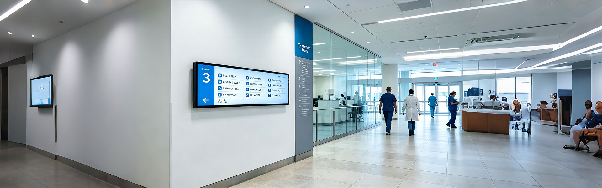
Floor Information Bar LCD Display Solution
Ultra-wide, high-brightness stretched bar LCD disp...
view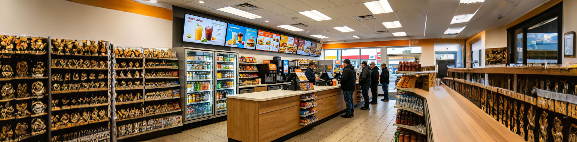
Convenience Store Bar LCD Display Solution
Ultra-slim, high-brightness stretched bar LCD disp...
view
Bus Passenger Information Stretched Bar Display Solution
A rugged, ultra-wide stretched bar display solutio...
viewRelated Products
You may also be interested in the following products