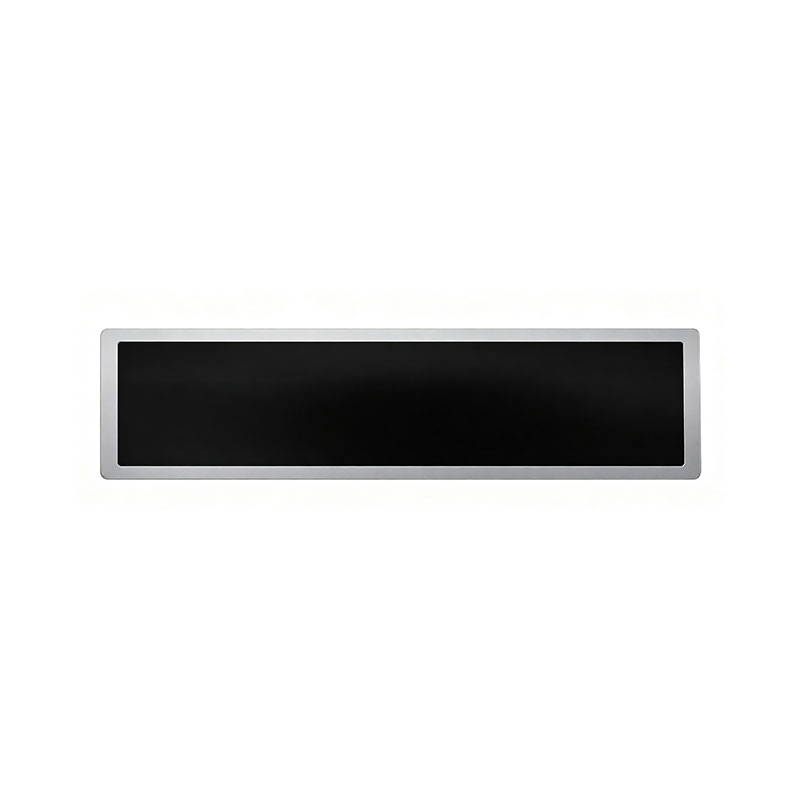
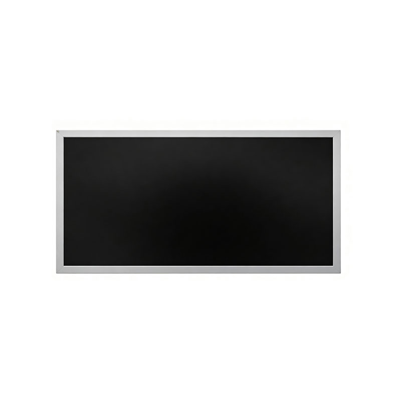
22.7 Inch Bar Form LCD Module | Panel | display
MODEL: HT227HBM
Need customized solution?
Our engineering team is always ready to provide you with professional technical support and flexible customized services.
Understand light customization servicesBuilt by us. Configured for you.
HITULCD supplies LCD modules and display solutions directly from our manufacturing operation, giving OEMs, integrators and distributors direct access to engineering, customization and production.
Supply
Supplier Qualification
VerificationTechnical Specifications
| LCD PANEL PARAMETERS | DRIVER BOARD SPECIFICATIONS | ||
|---|---|---|---|
| ITEM | DETAILS | ITEM | DETAILS |
| Model Number | HT227HBM | Input Interface | LVDS, 30 Pins |
| Brand | HITULCD | Signal Type | LVDS |
| Product Series | 23.8" Cut Panel Series | OSD KEYS | Depends on LVDS controller |
| Diagonal Size | 22.7" Cut Stretched Bar (Cut from 23.8" Panel, 3/4 Cut) | OSD CONTROL | Depends on LVDS controller |
| Resolution | 1920 × 810, Aspect Ratio 21:9 | ||
| Product Category | Graphic Type Display | ||
| Panel Type | a‑Si TFT‑LCD, Complete LCM Module | ||
| Physical Shape | Flat Rectangle | ||
| Display Area (A.A) | 531.36(W) × 224.17(H) mm | ||
| Overall Dimension | 561.36(W) × 254.17(H) mm | ||
| Max Thickness | 20 mm | ||
| LCD Technology | IPS, Transmissive Polarizer | ||
| Typical Brightness | 1000 NITS (Customizable: 300~1000 NITS) | ||
| Transmissive Contrast Ratio | Not specified | ||
| Viewing Angle | 89°/89°/89°/89°(Min.)(L/R/U/D) | ||
| Viewing Direction | Full Viewing Angle | ||
| Display Colors | 16.7M Colors | ||
| Backlight Type | WLED | ||
| Touch Panel | Without Touch Function | ||
| Application Fields | Digital Signage, Cut Stretched Bar Displays | ||
| Operating Temperature | 0 ~ 50 °C | ||
| Storage Temperature | -20 ~ 70 °C | ||
Custom Bar-Type LCD Cutting Service — OEM/ODM, Any Standard Panel Size
One Engineering Partner for Every Non-Standard Aspect Ratio, From 8" to 88"
Overview
Most bar-type / stretched-aspect-ratio LCD requirements don't start from a catalog part number — they start from a mounting cavity: a shelf depth, a pillar width, an elevator jamb, a vehicle dashboard cutout. Standard 16:9 panels rarely fit that geometry.
HituLCD's custom cutting service takes any standard TFT-LCD panel size and precision-trims it along one axis to match your exact mechanical envelope — turning a mass-produced base cell into a purpose-built bar display, without the cost and lead time of a fully custom glass tooling program.
This is not a single-SKU product — it's an engineering service. If you can specify the outline, we will assess whether it can be cut, from which base panel, and at what tolerance and cost.
Size Range We Work With
| Category | Range | Notes |
|---|---|---|
| Full stretched-bar product range | 8" to 88" diagonal | Custom aspect ratios, brightness, and interface per project |
| Commonly cuttable base panel models | 18.5", 21.5", 23.8", 27", 32", 40" | Proven cut process, fastest turnaround, lowest NRE |
| Custom aspect ratios | 4:1, 8:1, 16:3, 16:4.5, 32:9, and other non-standard ratios | Available for OEM orders of 50+ units |
| Orientation | Landscape or portrait | Mechanical drawing confirms feasibility |
If your target size falls outside the commonly cuttable list, our engineering team will still evaluate feasibility against the nearest available base panel — send your outline drawing and we will confirm.
Why Cut Instead of Fully Custom Tooling?
| Custom Cut (Base Panel + Trim) | Fully Custom Glass Design | |
|---|---|---|
| NRE cost | Low — cutting fixture + DFM only | High — new cell/array tooling |
| Sample lead time | Weeks | Months |
| MOQ | From 50 pcs | Typically thousands |
| Design flexibility | One-axis trim within base panel limits | Full freedom, any ratio/size |
| Best for | Most bar/shelf/signage/HMI applications | Extreme ratios or ultra-high volume programs |
For the majority of retail, transportation, elevator, vending, and industrial HMI projects, a custom cut from an existing base panel delivers the required form factor at a fraction of the cost and time of ground-up tooling — which is why it's our core service.
How the Program Works
Share your outline — target dimensions or drawing (DWG/DXF/STEP), orientation, and mounting constraints
DFM feasibility review — our engineers select the nearest base panel and confirm the cut line clears the Gate/Source driver routing and active TFT array
Cutting method recommendation — mechanical wheel cutting or ultrafast laser cutting, selected based on tolerance and proximity to the active area
Engineering samples — first-article samples produced and edge-sealed for your validation, including optical (light leakage / Mura) and mechanical (edge integrity) inspection
Reliability qualification — samples tested against the agreed environmental/mechanical standard (damp heat, thermal shock, drop) before process lock
Mass production release — MOQ from 50 pcs, with quality documentation issued per batch
Cutting & Process Capability
Mechanical wheel (scribe-and-break) cutting — lower cost, shorter lead time, typical tolerance ±0.2–0.3 mm; suited to cut lines outside the active display area
Ultrafast laser cutting — higher precision, minimal micro-cracking and heat-affected zone, typical tolerance ±0.05–0.1 mm; used when the cut line approaches the active array or driver IC
Edge sealing — UV-curable dispensed sealant applied post-cut to prevent liquid-crystal leakage and moisture ingress
Driver re-mapping — timing/driver board reconfigured where the cut removes part of the original active area, so the retained area displays correctly at native resolution
Reliability Standards We Test Against
| Test | Standard Reference | Purpose |
|---|---|---|
| Damp heat ("double-85") | IEC 60068-2-78 / JEITA ED-4701/100 | Moisture/humidity resistance of the sealed edge |
| Thermal shock / temperature cycling | IEC 60068-2-14 | Edge seal and glass integrity across temperature swings |
| High/low temperature storage & operation | Per selected commercial/industrial grade | Field environment survivability |
| Mechanical shock / drop | IEC 60068-2-27, ISTA / MIL-STD-810 style | Packaged-unit ruggedness |
Consumer-grade or industrial-grade qualification is selected per application; benchmark data from comparable cutting projects can be shared under NDA.
Brightness, Interface & Customization Options
Brightness: 500–1,000 nits standard for indoor/mixed-light use; up to 1,500–2,000+ nits for semi-outdoor or window-facing installations
Interface: HDMI, LVDS, or eDP, with driver board customization included
Touch: PCAP touch overlay with optical bonding available
Cover lens: custom shape, thickness, AR/AG coating
Branding: logo printing, custom FFC/connector length, private-label packaging
Cost, Yield & Lead Time
| Item | Typical Range | Notes |
|---|---|---|
| NRE (cutting fixture + DFM) | Quoted per project | Depends on cut complexity and method |
| First-sample lead time | 2–4 weeks | From drawing confirmation to sample shipment |
| Mass-production yield | 85–90% (mechanical) / 90–95%+ (laser) | Depends on cut geometry and proximity to active area |
| MOQ | 50 pcs | Standard across the cuttable series |
Typical Applications
Retail shelf-edge and smart shelf-label displays
Elevator, lobby, and corridor signage
Transit, bus-stop, and subway passenger information displays
Vending machines and self-service kiosks
Industrial control panels and machine HMI
Vehicle dashboard and in-cabin displays
What to Send for a Quotation
Target outline drawing (DWG/DXF/STEP) or dimensions and orientation
Nearest known standard panel size, if any (18.5"/21.5"/23.8"/27"/32"/40" or other)
Required brightness, interface, and operating temperature grade
Application environment (indoor / semi-outdoor / vibration-exposed)
Estimated annual volume
Send your outline and target environment, and HituLCD's engineering team will return a DFM feasibility assessment, recommended cutting method, and formal quotation covering NRE, sample lead time, and mass-production terms — for any bar-format size from 8" to 88".
23.8" Bar-Form LCD Module Panel Display (Cuttable / Stretched Bar Series)
Custom Ultra-Wide Aspect Ratio TFT-LCD Module | OEM/ODM | MOQ 50 pcs
Overview
The 23.8" Bar-Form LCD Module is built from a standard 23.8" a-Si TFT-LCD panel (1920×1080 FHD base cell) that is precision-cut along one axis to produce a non-standard, elongated "stretched bar" form factor — ideal for retail shelf-edge signage, transportation displays, elevator/lobby panels, vending fronts, and industrial control interfaces where a conventional 16:9 panel simply won't fit the available mounting space.
Because the cut is performed on a mass-produced base cell rather than a fully custom tooling run, customers get near-custom mechanical geometry at a fraction of the cost and lead time of a ground-up custom panel design.
Note: Final active area, resolution, and aspect ratio depend on the customer's specified cut line and are confirmed during the DFM (Design-for-Manufacturing) review. The values below reflect the base 23.8" panel and typical cut ranges; final specification is issued per project via a signed spec confirmation sheet.
Key Features
Custom aspect ratio — trimmed on one axis (width or height) from the base 23.8" FHD cell; typical resulting ratios include 8:1, 16:3, 16:4.5, and other bar/stretched formats per customer drawing
High-brightness options — 500–1,000 nits standard range for mixed-light retail/transit environments; up to 1,500–2,000 nits available for semi-outdoor or window-facing installations¹
Interface flexibility — HDMI, LVDS, or eDP signal input available; driver board re-mapping included where the cut removes part of the active array
Industrial-grade reliability — wide operating temperature options and long-life LED backlight (see Reliability section)
OEM/ODM support — custom brightness, resolution/timing, interface, cover lens bonding, logo branding, and private-label packaging
Optional touch — PCAP touch overlay available on request (with optical bonding for outdoor/high-vibration use)
Technical Specifications
| Parameter | Base Panel (Pre-Cut) | Typical Cut Range | Notes |
|---|---|---|---|
| Base panel size | 23.8" diagonal | — | Standard a-Si TFT-LCD cell |
| Base resolution | 1920 × 1080 (FHD), 16:9 | Reduced proportionally to the retained active area after cut | Final resolution confirmed per cut line |
| Base active area | ≈ 527.0 (W) × 296.5 (H) mm² | One axis trimmed per customer spec | ±0.3 mm typical machining tolerance¹ |
| Pixel pitch | ≈ 0.2745 mm | Unchanged on the retained axis | — |
| Brightness (luminance) | 250 cd/m² (base panel, typ.) | 500 / 700 / 1,000 / 1,500 nits (custom backlight) | Selected per application; see Applications table |
| Contrast ratio | 1000:1 (typ.) | Unchanged | — |
| Viewing angle | 89/89/89/89° (typ., all directions) | Unchanged | Symmetric viewing |
| Color depth | 8-bit, 16.7M colors | Unchanged | RGB vertical stripe |
| Backlight type | Edge-lit WLED | Edge-lit or direct-lit (high-brightness variants) | 50,000 hrs rated life¹ |
| Interface | LVDS (2-ch, 8-bit) | LVDS / HDMI / eDP available | Driver board customization included |
| Operating temperature | 0°C to +50°C (commercial grade) | −20°C to +70°C (industrial grade, optional)¹ | Confirm grade at RFQ stage |
| Storage temperature | −20°C to +60°C¹ | −30°C to +80°C (industrial grade)¹ | — |
| Module depth | ≈ 13 mm (base) | Depends on backlight driver stack | Slim profile options available |
| Cover lens / bonding | Optional | Air-gap or full optical bonding | Recommended for touch/outdoor use |
| MOQ | — | 50 pcs (custom-cut panels) | Standard across HituLCD cuttable series |
¹ International standard / typical industry reference value — to be confirmed in writing by HituLCD's engineering team against your specific cut geometry and application environment.
Customization & OEM/ODM Services
Custom cut dimensions (one-axis trim) within the panel's mechanical limits
Custom brightness tuning (500–1,500+ nits)
Interface conversion: HDMI, LVDS, eDP
PCAP touch integration with optical bonding
Custom cover glass shape, thickness, and AR/AG coating
Logo printing, custom FFC/connector length, custom packaging and labeling for private-label brands
Full DFM support: mechanical drawing review, gerber/pinout confirmation, and pre-production sample approval
Typical Applications
| Application | Recommended Brightness | Environment |
|---|---|---|
| Retail shelf-edge / smart shelf labels | 500–700 nits | Indoor, mixed lighting |
| Elevator, lobby, and corridor signage | 500–1,000 nits | Indoor |
| Transit / bus-stop / subway signage | 700–1,000 nits | Semi-outdoor, covered |
| Window-facing retail displays | 1,000–1,500 nits | Indoor with high ambient light |
| Vending machines & kiosks | 500–1,000 nits | Indoor |
| Industrial control panels / HMI | 500–1,000 nits, wide-temp | Industrial, 24/7 duty cycle |
Ordering Information
Sample / prototype run: first article samples available (see FAQ for lead time)
MOQ (mass production): 50 pcs minimum for custom-cut geometry; higher volumes reduce per-unit tooling amortization
Lead time: confirmed at quotation stage based on cut complexity, brightness tier, and interface customization
Quality documentation: inspection report, reliability test summary, and COC (Certificate of Conformance) provided with each production batch on request
Technical FAQ — For Engineers, Procurement & Project Managers
1. Cutting Process & Feasibility
Q: What cutting method do you recommend, and what tolerances can I expect?Two processes are available depending on precision and volume requirements:
Mechanical wheel (scribe-and-break) cutting — lower cost, shorter lead time, suitable for straight-line cuts outside the active display area; typical tolerance ±0.2–0.3 mm.
Ultrafast (UV/femtosecond) laser cutting — higher precision, cleaner edge, minimal heat-affected zone and micro-cracking; typical tolerance ±0.05–0.1 mm; recommended when the cut line approaches the active area or a driver IC.
The recommended method is confirmed after reviewing your target dimensions and tolerance requirements.
Q: Will the cut interfere with the Gate/Source trace routing or the TFT array?It can, if the cut line falls inside the routing margin. Our DFM review checks the cut line against the base panel's Gate driver, Source driver, and TFT array boundaries before quotation to confirm the retained active area is fully addressable and free of open/short risk.
Q: What drawings or parameters do you need from us to assess feasibility?Typically:
Target outline dimensions (or the finished bar/panel drawing, DWG/DXF/STEP)
Required active area and orientation (portrait/landscape)
Interface preference (HDMI/LVDS/eDP) and connector location constraint, if any
Target brightness and operating temperature range
Intended mounting method / enclosure depth
Application environment (indoor, semi-outdoor, vibration/shock exposure)
Q: What edge-flatness and micro-crack standards apply after cutting?Edge inspection follows standard optical-glass edge criteria: no visible chipping beyond a defined edge zone (typically ≤0.1 mm chip depth under laser cutting), no through-thickness cracks, and edge flatness controlled to avoid stress concentration during subsequent handling and mounting. Full inspection criteria are documented in the process spec issued after sample approval.
2. Reliability & Edge Sealing
Q: How do you seal the cut edge against liquid crystal leakage and moisture ingress?A secondary edge-sealing process is applied after cutting — typically UV-curable dispensed sealant applied along the cut edge, cured under UV light to form a moisture and LC-leakage barrier. Sealant selection and dispensing pattern are validated against the reliability test plan below before mass production release.
Q: Can the cut module pass standard reliability testing, and do you have benchmark data?Cut modules are tested against the same class of environmental and mechanical standards used for standard TFT-LCD modules, for example:
Damp heat (double-85 / "85/85") test — IEC 60068-2-78 or JEITA ED-4701/100, typically 85°C / 85% RH for 96–500 hours depending on grade
Thermal shock / temperature cycling — IEC 60068-2-14, e.g., −20°C ↔ +60°C or −30°C ↔ +70°C, multiple cycles
High/low temperature storage & operation — per the operating/storage temperature range selected
Mechanical shock / drop test — IEC 60068-2-27 (shock) or ISTA/MIL-STD-810 style drop test for packaged units
Whether the module targets consumer-grade or industrial-grade qualification depends on your application; the applicable test plan and pass/fail criteria are agreed at the project kickoff and benchmark reports from comparable prior cutting projects can be shared under NDA.
Q: Is there any risk of light leakage or color shift (Mura) near the sealed edge after cutting?This is a known risk area for cut panels and is specifically why edge sealing and backlight re-masking are controlled steps in the process. With correct laser-cut edge quality and sealant dispensing, edge light leakage and Mura are controlled to within the same acceptance criteria used for standard panel edge inspection. Engineering samples are used to visually and instrumentally verify this before mass production sign-off.
3. Cost, Yield & Lead Time
Q: What is the typical NRE cost and first-sample lead time?NRE (cutting fixture, DFM review, and process validation) is quoted per project based on cut complexity and cutting method. As a general industry reference, first-article samples (around 20 pcs) typically require 2–4 weeks from drawing confirmation to sample shipment; exact NRE and lead time are confirmed in the formal quotation.
Q: What yield should we expect in mass production, and what is the MOQ?Mechanical wheel cutting typically yields in the 85–90% range; laser cutting typically yields 90–95%+, depending on cut geometry and proximity to the active area. MOQ for custom-cut panels is 50 pcs; production lead time and yield commitments are formalized after the engineering sample is approved and the process is locked.
Contact & Next Steps
To receive a formal quotation, please provide:
Target outline drawing (DWG/DXF/STEP) or dimensions and orientation
Required brightness, interface, and operating temperature grade
Intended application and mounting environment
Estimated annual volume
HituLCD's engineering team will return a DFM feasibility assessment, recommended cutting method, and formal quotation including NRE, sample lead time, and mass-production terms.
Know The Terms Before You Inquire.
|
01 — Shipping Terms
Incoterms Available
EXW
Ex Works — pick up from our factory
FOB
Free On Board — most common for ocean freight
CIF
Cost, Insurance & Freight — to your port
|
02 — Order Minimum
MOQ: 1 Units
Applies to standard specs. Custom brightness, cutting or bezel may adjust MOQ, confirmed at quotation. Sample units available before bulk order
|
03 — Payment Protection
Multiple Secured Methods
|
A Real Factory. Publicly Verifiable.
|
Legal Company Name
Shenzhen Hantu Jiashi Technology Co., Ltd.
|
Unified Social Credit Code
91440300306068446B
|
|
Legal Representative
YUN CHEN
|
Registered Capital
RMB 2,000,000
|
|
Established
May 23, 2014 (11+ years operation)
|
Business Status
● Active / In Operation
|
|
Registered Factory Address
Building B, Gangshen Innovation Park, Huaning Road, Dalang Sub-district, Longhua District, Shenzhen, Guangdong, China
|
|
Contact HITULCD
We'll respond via email within 24 hours. If you'd like to discuss details over WhatsApp or a call, please leave a preferred time and contact method in your message — we will never call you unannounced.
Related solutions
This product is suitable for the following industry application scenarios
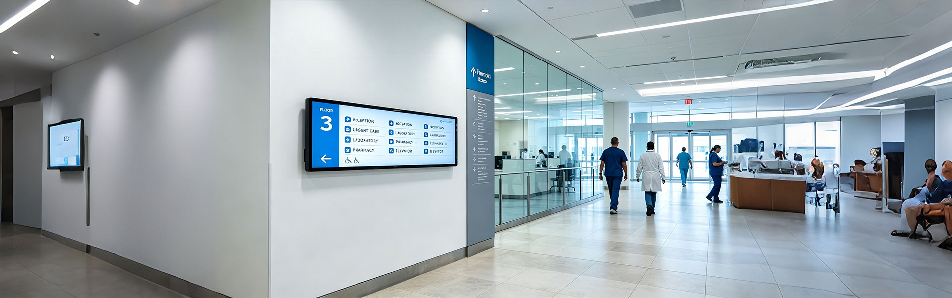
Floor Information Bar LCD Display Solution
Ultra-wide, high-brightness stretched bar LCD disp...
view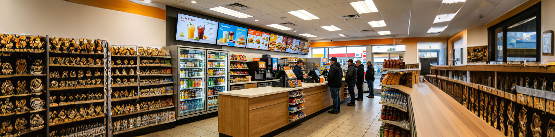
Convenience Store Bar LCD Display Solution
Ultra-slim, high-brightness stretched bar LCD disp...
view
Bus Passenger Information Stretched Bar Display Solution
A rugged, ultra-wide stretched bar display solutio...
viewRelated Products
You may also be interested in the following products