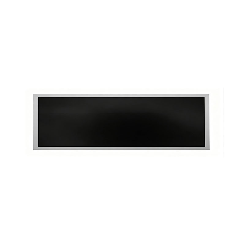
23.8 Inch Narrow elongated LCD panel
MODEL: HT238HBM
Need customized solution?
Our engineering team is always ready to provide you with professional technical support and flexible customized services.
Understand light customization servicesBuilt by us. Configured for you.
HITULCD supplies LCD modules and display solutions directly from our manufacturing operation, giving OEMs, integrators and distributors direct access to engineering, customization and production.
Supply
Supplier Qualification
VerificationTechnical Specifications
| LCD PANEL PARAMETERS | DRIVER BOARD SPECIFICATIONS | ||
|---|---|---|---|
| ITEM | DETAILS | ITEM | DETAILS |
| Model Number | HT238HBM | Input Interface | LVDS, 30 Pins |
| Brand | HITULCD | Signal Type | LVDS |
| Product Series | 27" Cut Panel Series | OSD KEYS | Depends on LVDS controller |
| Diagonal Size | 23.8" Cut Stretched Bar (Cut from 27" Panel, 1/4 Cut) | OSD CONTROL | Depends on LVDS controller |
| Resolution | 1920 × 270, Aspect Ratio 7.11:1 (>3:1) | ||
| Product Category | Graphic Type Display | ||
| Panel Type | a‑Si TFT‑LCD, Complete LCM Module | ||
| Physical Shape | Flat Rectangle | ||
| Display Area (A.A) | 597.6(W) × 84.04(H) mm | ||
| Overall Dimension | 627.6(W) × 114.04(H) mm | ||
| Max Thickness | 20 mm | ||
| LCD Technology | IPS, Transmissive Polarizer | ||
| Typical Brightness | 500 NITS (Customizable: 300~1000 NITS) | ||
| Transmissive Contrast Ratio | 1000:1 (Typ.) | ||
| Viewing Angle | 89°/89°/89°/89°(Min.)(L/R/U/D) | ||
| Viewing Direction | Full Viewing Angle | ||
| Display Colors | 16.7M Colors | ||
| Backlight Type | WLED | ||
| Touch Panel | Without Touch Function | ||
| Application Fields | Digital Signage, Cut Stretched Bar Displays | ||
| Operating Temperature | 0 ~ 50 °C | ||
| Storage Temperature | -20 ~ 70 °C | ||
OEM/ODM Custom-Cut Bar LCD Display Solutions
One Source Panel Platform. Any Bar Display Size You Need.
Overview
Most stretched-bar LCD suppliers offer a fixed catalog of sizes — 19", 23.8", 28", 35"... and if your project needs something in between, or something no one else stocks, you're stuck redesigning your enclosure around their glass instead of the other way around.
We work differently. As an OEM/ODM manufacturing partner, we cut bar-type LCD panels to your exact dimensions, not the other way around. Whatever aspect ratio, active area, or resolution your project calls for, we start from the right source mother glass and cut, seal, and qualify it to your specification — so your enclosure design drives the panel, not the reverse.
What "Any Size" Actually Means
| Your Requirement | Our Capability |
|---|---|
| Source panel size range | 7" to 98"+ mother glass, sourced from major panel makers (LG, AUO, BOE, CSOT, Innolux, and others per availability) |
| Aspect ratio | Fully custom — from mild elongation (e.g., 8:3) to extreme bar ratios (16:3, 32:9, and beyond) |
| Cut orientation | Horizontal or vertical bar formats |
| Resolution mapping | Custom resolution re-mapped to your cut active area |
| Brightness | Standard (250–350 cd/m²) up to high-brightness (700–1500 cd/m²) backlight configurations |
| Touch integration | PCAP touch overlay available on cut panels |
| Panel technology | IPS/AHVA, VA, and TN options depending on source panel availability |
| Interface | LVDS, eDP, or MIPI, matched to your driver board |
| Control electronics | Bare panel only, or fully integrated with Android media player / custom mainboard |
If a standard off-the-shelf panel doesn't exist in your target size — that's exactly the project we're built for.
How Custom Cutting Works
Spec & Drawing Review — send your target active area, aspect ratio, resolution, and enclosure constraints. Even a rough sketch or mechanical drawing is enough to start.
Source Panel Selection — we identify the mother glass that best fits your target dimensions with minimal waste and optimal cut-line placement relative to the panel's Gate/Source circuitry.
Feasibility & Tolerance Confirmation — our engineering team confirms recommended cutting method (mechanical wheel or ultra-fast laser), achievable tolerance, and any keep-out constraints near active circuitry.
Cutting, Sealing & Requalification — panels are precision-cut, edge-sealed to prevent liquid crystal leakage and moisture ingress, and re-tested for uniformity, Mura, and edge light-leakage.
Sample Build & Validation — first samples (typ. 2–4 weeks from spec confirmation) go through functional and environmental spot-checks before you sign off.
Mass Production Ramp — once samples are approved, we scale to your volume with the same process controls, backed by full reliability documentation.
Why OEM/ODM Buyers Choose Us
No fixed-catalog ceiling — your project defines the panel size, not our inventory
Single accountable partner — cutting, edge-sealing, optical requalification, and reliability testing all under one roof, instead of coordinating separate vendors for glass-cutting and sealing
Engineering-led feasibility review — every cut is checked against the source panel's internal circuitry layout before quoting, avoiding costly redesigns after tooling starts
Documented reliability — cut-and-sealed panels are qualified against standard environmental protocols (high-temp/high-humidity, thermal shock, drop/vibration) with test reports available on request
Flexible integration — bare panel, framed module, or fully integrated smart-signage unit with Android board, Wi-Fi/LAN, and remote content management
Scalable from prototype to volume — low-MOQ sampling for design validation, with a clear path to mass-production pricing and lead times
Typical Applications for Custom-Sized Bar Displays
Retail shelf-edge and price-strip signage (any shelf depth/height)
OEM digital signage products built around a proprietary enclosure
Transit, elevator, and wayfinding displays with non-standard mounting constraints
Kiosk and vending equipment with fixed internal cavity dimensions
Architectural and hospitality installations requiring a specific sightline width
Industrial control-room status bars and instrument panels
Engineering Support for Your Project
Before you commit to a panel size, our team can help you:
Validate whether your target dimensions are achievable from available mother glass sizes, and recommend the most cost-efficient source panel
Advise on cutting method and expected tolerance for your specific cut-line geometry
Share reference reliability test data from comparable prior cutting projects
Provide budgetary NRE, unit pricing, and MOQ guidance based on your projected volume
Start Your Custom Project
Send us:
Target active area / outline dimensions (or your enclosure drawing)
Desired aspect ratio and resolution
Application environment (indoor/outdoor, temperature range)
Estimated sample and annual volume
Our engineering team will return a feasibility assessment and budgetary quotation within 1–2 business days.
No standard size fits your project? That's the project we want.
Custom-Cut Narrow Bar LCD Panels: Technical Q&A for Engineers & Procurement Teams
A practical reference for sourcing and procurement teams evaluating cut/elongated TFT-LCD panels — covering cutting feasibility, sealing reliability, and cost/yield expectations before you finalize your panel specification.
1. Cutting Process & Feasibility
What cutting method do you recommend for my panel — mechanical wheel-cutting or ultra-fast laser cutting?
The right method depends on your target cut-line tolerance, edge finish requirement, and cut geometry:
Mechanical wheel (scribe-and-break) cutting — cost-effective, mature process, well suited to straight-line cuts with standard tolerance requirements (typ. ±0.2–0.3 mm). Preferred for high-volume, straightforward bar-shaped cuts.
Ultra-fast (femtosecond/picosecond) laser cutting — delivers tighter tolerances (typ. ±0.05–0.1 mm), a cold-cutting process with minimal micro-crack propagation, and can handle more complex or curved cut lines. Recommended when your cut line is close to active circuitry, when edge chipping must be minimized, or when tolerance requirements exceed what wheel-cutting can reliably hold.
We confirm the recommended method during design review, based on your drawing and tolerance callouts.
Will the cut line interfere with the Gate/Source traces or the TFT array area of the original panel?
This is assessed on a panel-by-panel basis against the source panel's internal layout (Gate driver, Source driver, and TFT array boundaries). Cutting too close to active circuitry risks trace damage, signal integrity issues, or dead zones near the cut edge. We map your requested cut line against the panel's internal architecture before quoting to confirm there is sufficient keep-out margin.
What drawings or parameters do you need from us to confirm cutting feasibility at the evaluation stage?
To run a feasibility assessment, please provide:
Target cut dimensions (final active area / outline dimensions) with tolerance requirements
Desired aspect ratio and resulting resolution (if the display will be re-mapped)
Cut-line location relative to the panel's reference edge (mechanical drawing or sketch is acceptable at this stage)
Mounting/enclosure constraints (bezel, connector exit direction, cable length)
Target application environment (indoor/outdoor, expected operating temperature range)
Project volume (sample quantity and projected annual volume) — this affects which cutting method and tooling investment makes sense
What is your edge flatness and micro-crack control standard after cutting?
Cut edges are inspected for flatness and chip/crack size under magnification against internal acceptance criteria before a panel proceeds to sealing. Panels with visible chipping beyond the defined micro-crack tolerance, or edge flatness deviation outside the agreed tolerance band, are rejected at this stage rather than passed to sealing — this keeps sealing yield and downstream reliability predictable. Specific numeric criteria are shared as part of the formal process spec once cutting method and tolerance class are confirmed for your project.
2. Reliability & Edge-Sealing Assurance
How do you prevent liquid leakage and moisture ingress at the cut edge (sealing process)?
After cutting, the exposed edge undergoes a secondary sealing process — typically UV-cure adhesive dispensing along the cut line, applied and cured under controlled dispensing parameters (bead width, cure time/intensity) to fully encapsulate the liquid crystal layer and glass edge. This is followed by a visual/AOI inspection of the seal bead for voids or incomplete coverage before the panel proceeds to functional test. Alternative sealing media (e.g., epoxy-based sealants) can be used depending on the application's environmental exposure requirements — this is confirmed during process qualification.
Can the cut TFT module pass standard reliability testing (consumer-grade / industrial-grade)?
Yes — cut-and-sealed panels are qualified against standard environmental and mechanical reliability protocols before release to production. Typical qualification testing referenced for this panel class includes:
| Test | Typical Condition (reference) |
|---|---|
| High-temp / high-humidity (double 85) | 85°C / 85% RH, 96–500 hrs depending on grade |
| High-temperature storage/operation | 60–70°C, 240–500 hrs |
| Low-temperature storage/operation | -20°C to -30°C, 240–500 hrs |
| Thermal shock | -20°C ↔ 60°C, 30–100 cycles |
| Mechanical drop test | Per packaged-unit drop height per ISTA/ASTM-referenced procedure |
| Vibration | Per IEC 60068-2-6 random/sine vibration reference profile |
Grade selection (consumer vs. industrial) determines exact duration/cycle count and is agreed with you at the quotation stage based on your end-use environment. We're happy to share test reports from comparable prior cutting projects as reference benchmark data on request — please specify your target application so we can share the most relevant dataset.
Does the cut and sealed edge cause light leakage or color shift (Mura) at the border?
Edge light leakage and border Mura are the primary optical risks in any cut-panel process, driven mainly by backlight light-guide-plate behavior near the new edge and seal-bead uniformity. Our process addresses this through:
Backlight/light-guide adjustment (or edge masking) calibrated to the new panel boundary
Controlled, uniform seal-bead application to avoid uneven light scattering at the edge
100% visual/AOI inspection for edge leakage and border color shift before packing, against an internal Mura acceptance standard
Some residual edge effect is a known characteristic of cut-panel technology; it is minimized through process control but should be evaluated against your specific ambient lighting/viewing conditions during sample approval.
3. Cost, Yield & Lead Time
What is the approximate NRE cost to start a custom cutting project, and how long does first-sample production (e.g., 20 pcs) take?
NRE (tooling/fixture setup, cutting-path programming, sealing-process qualification) is quoted per project based on cut complexity, chosen cutting method, and whether a new fixture is required — please send your target specification for a firm quotation. Typical first-sample lead time is 2–4 weeks from drawing/spec confirmation and PO, covering source panel procurement, cutting, sealing, curing, and functional/reliability spot-check before shipment. Complex geometries or panels requiring new fixture tooling may run longer; we'll confirm an exact timeline at quotation.
Based on your experience, what mass-production yield can we expect for this type of cutting project, and what is your MOQ?
Mass-production yield for cut-panel processes is influenced by cut-line complexity, tolerance class, and proximity to active circuitry — tighter tolerances and cuts near the array boundary generally run lower yield than straightforward straight-line bar cuts. We share yield expectations specific to your confirmed design once the sample build and process qualification are complete, since this is the most reliable basis for a mass-production yield commitment. MOQ is set per project based on cutting method (wheel-cut vs. laser) and source panel sourcing lot size — please share your target annual volume so we can propose an MOQ aligned with your program size.
Next Step
Send us your target cut dimensions, aspect ratio, application environment, and estimated volume, and our engineering team will return a feasibility assessment, budgetary NRE/unit pricing, and a first-sample lead time within 1–2 business days.
Know The Terms Before You Inquire.
|
01 — Shipping Terms
Incoterms Available
EXW
Ex Works — pick up from our factory
FOB
Free On Board — most common for ocean freight
CIF
Cost, Insurance & Freight — to your port
|
02 — Order Minimum
MOQ: 1 Units
Applies to standard specs. Custom brightness, cutting or bezel may adjust MOQ, confirmed at quotation. Sample units available before bulk order
|
03 — Payment Protection
Multiple Secured Methods
|
A Real Factory. Publicly Verifiable.
|
Legal Company Name
Shenzhen Hantu Jiashi Technology Co., Ltd.
|
Unified Social Credit Code
91440300306068446B
|
|
Legal Representative
YUN CHEN
|
Registered Capital
RMB 2,000,000
|
|
Established
May 23, 2014 (11+ years operation)
|
Business Status
● Active / In Operation
|
|
Registered Factory Address
Building B, Gangshen Innovation Park, Huaning Road, Dalang Sub-district, Longhua District, Shenzhen, Guangdong, China
|
|
Contact HITULCD
We'll respond via email within 24 hours. If you'd like to discuss details over WhatsApp or a call, please leave a preferred time and contact method in your message — we will never call you unannounced.
Related solutions
This product is suitable for the following industry application scenarios
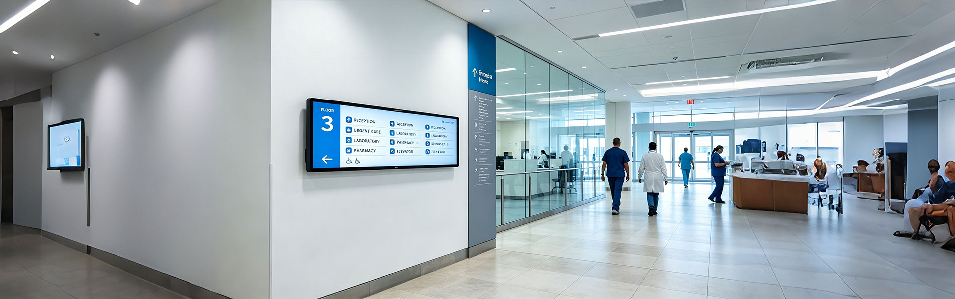
Floor Information Bar LCD Display Solution
Ultra-wide, high-brightness stretched bar LCD disp...
view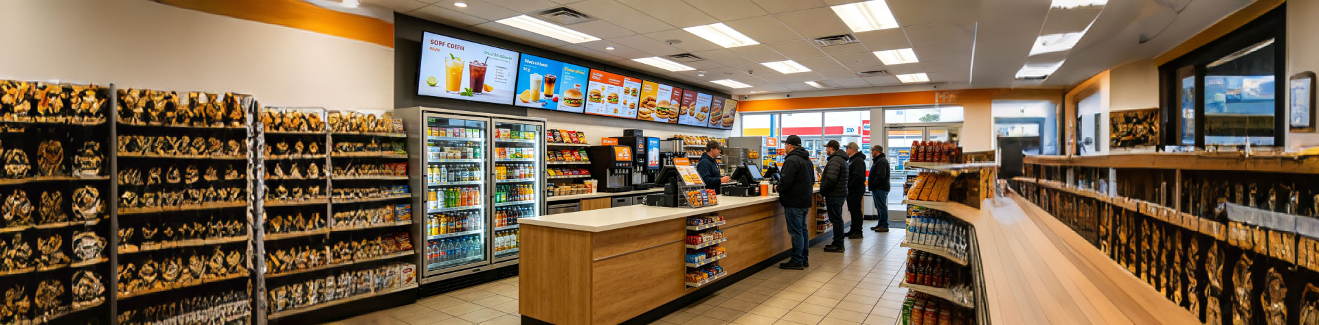
Convenience Store Bar LCD Display Solution
Ultra-slim, high-brightness stretched bar LCD disp...
view
Bus Passenger Information Stretched Bar Display Solution
A rugged, ultra-wide stretched bar display solutio...
viewRelated Products
You may also be interested in the following products