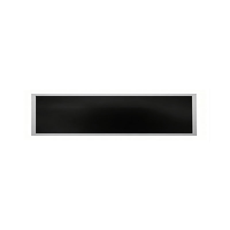
25.1 Inch Narrow Ultra Wide TFT LCD Module
MODEL: HT251HBM
Need customized solution?
Our engineering team is always ready to provide you with professional technical support and flexible customized services.
Understand light customization servicesBuilt by us. Configured for you.
HITULCD supplies LCD modules and display solutions directly from our manufacturing operation, giving OEMs, integrators and distributors direct access to engineering, customization and production.
Supply
Supplier Qualification
VerificationTechnical Specifications
| LCD PANEL PARAMETERS | DRIVER BOARD SPECIFICATIONS | ||
|---|---|---|---|
| ITEM | DETAILS | ITEM | DETAILS |
| Model Number | HT251HBM | Input Interface | LVDS, 30 Pins |
| Brand | HITULCD | Signal Type | LVDS |
| Product Series | 27" Cut Panel Series | OSD KEYS | Depends on LVDS controller |
| Diagonal Size | 25.1" Cut Stretched Bar (Cut from 27" Panel, 2/3 Cut) | OSD CONTROL | Depends on LVDS controller |
| Resolution | 1920 × 720, Aspect Ratio 8:3 | ||
| Product Category | Graphic Type Display | ||
| Panel Type | a‑Si TFT‑LCD, Complete LCM Module | ||
| Physical Shape | Flat Rectangle | ||
| Display Area (A.A) | 597.6(W) × 224.1(H) mm | ||
| Overall Dimension | 627.6(W) × 254.1(H) mm | ||
| Max Thickness | 20 mm | ||
| LCD Technology | IPS, Transmissive Polarizer | ||
| Typical Brightness | 1000 NITS (Customizable: 300~1000 NITS) | ||
| Transmissive Contrast Ratio | 1000:1 (Typ.) | ||
| Viewing Angle | 89°/89°/89°/89°(Min.)(L/R/U/D) | ||
| Viewing Direction | Full Viewing Angle | ||
| Display Colors | 16.7M Colors | ||
| Backlight Type | WLED | ||
| Touch Panel | Without Touch Function | ||
| Application Fields | Digital Signage, Cut Stretched Bar Displays | ||
| Operating Temperature | 0 ~ 50 °C | ||
| Storage Temperature | -20 ~ 70 °C | ||
Custom-Cut Stretched Bar TFT LCD: Engineering & Sourcing Capability Brief
For engineers, procurement managers, and project leads evaluating a custom bar-format LCD cutting project.
Sourcing a non-standard, narrow-format TFT panel — whether cut from an existing standard cell or engineered as a fully custom bar-type module — raises a consistent set of feasibility, reliability, and commercial questions before a program can move forward. This brief answers the questions our B2B partners raise most often during technical evaluation, so your team can move from concept to sample with a clear picture of process, risk, and timeline.
Figures below reflect standard industry practice for this process class. Project-specific numbers (NRE, yield, MOQ, lead time) are confirmed against your drawing and volume at RFQ stage — treat the ranges here as planning references, not final quotation.
1. Cutting Process & Feasibility
Which cutting method do you recommend — mechanical wheel cutting or laser cutting?
Method selection depends on target dimensional tolerance and the base cell's array design:
Mechanical wheel (scribe-and-break) cutting — lower cost, shorter lead time, suitable for straight-line cuts outside the active display area with standard tolerance requirements (typically ±0.2–0.3 mm).
Ultra-fast (picosecond/femtosecond) laser cutting — used when the cut line runs close to the active area, when tighter tolerance is required (±0.05–0.1 mm), or when micro-crack control is critical for downstream sealing and reliability. Laser cutting adds cost and lead time but significantly reduces edge stress and particulate contamination risk.
We confirm the recommended method once we have your target dimensions and tolerance requirement.
Will the cut interfere with the Gate/Source trace routing or the active TFT array?
This is evaluated case-by-case against the base cell's layout. What we need from you to complete a feasibility assessment:
Target outline dimensions and cut-line position (relative to the panel's active area)
Required tolerance / dimensional drawing (2D CAD or PDF acceptable for initial review)
Base panel model number, if a specific source cell is already identified
Interface requirement (LVDS/HDMI/etc.) and any connector-position constraints
With this information, our engineering team maps the cut line against the Gate/Source driver IC and array layout to confirm whether the cut is achievable without circuit interference, and flags any area where the cut line must be adjusted.
What is your edge flatness and micro-crack control standard after cutting?
Post-cut edges are inspected against standard optical-glass edge criteria — edge chipping, flatness, and micro-crack propagation are controlled within process-defined limits and verified under microscope inspection before sealing. Specific acceptance criteria (chip size, crack length tolerance) are documented in the process spec provided at sample approval.
2. Reliability & Edge Sealing
How do you prevent liquid crystal leakage and moisture ingress after cutting?
Cut edges go through a secondary sealing process — typically UV-cure adhesive dispensing along the cut edge, applied and cured under controlled dispensing parameters to fully encapsulate the exposed edge. Depending on project requirements, additional edge coating or potting can be added for higher ingress-protection targets.
Can the cut module pass standard reliability testing?
Yes — cut-and-sealed modules are validated against standard consumer- or industrial-grade reliability protocols depending on the target application. Typical test references include:
| Test | Typical Standard Reference | Purpose |
|---|---|---|
| High-temperature / high-humidity ("double 85") | 85°C / 85% RH, 96–240 hrs (IEC 60068-2-67 or equivalent) | Long-term humidity and thermal stress on seal integrity |
| High/low temperature storage & operation | -20°C to +70°C (operating), -30°C to +80°C (storage) | Confirms display function across operating environment |
| Thermal shock (cold/hot cycling) | -20°C ↔ +60°C, multiple cycles (per IEC 60068-2-14 or equivalent) | Verifies seal and bonding integrity under rapid temperature change |
| Mechanical drop test | Per packaging/mounting spec (e.g. MIL-STD-810 methodology as reference) | Structural robustness of the finished module/assembly |
We can share representative test data from comparable prior cutting projects once your target application and grade (consumer vs. industrial) are confirmed — this determines which test package applies.
Does the sealed edge cause light leakage or color shift (Mura) near the border?
Edge-zone optical performance is the main risk area in any cutting project, and it's managed through backlight design (edge light-guide adjustment) and consistent sealant dispensing width/height. A narrow inactive border is typically reserved outside the active display area specifically to absorb any edge-effect Mura, keeping it outside the viewable region. We review this against your specific active-area-to-edge distance during feasibility assessment.
3. Cost, Yield & Lead Time
What is the NRE cost to start a custom cutting project, and how long does first sampling take?
NRE (tooling/process setup) cost depends on cutting method, cut-line complexity, and whether a new fixture is required — this is quoted per project once the drawing is reviewed. As a planning reference:
Mechanical cutting projects: typically lower NRE, first sample (e.g. 20 pcs) in 2–3 weeks
Laser cutting projects: higher NRE due to fixture/process setup, first sample typically 3–4 weeks
Exact figures are confirmed in your formal quotation.
What yield should we plan for at mass production, and what's the MOQ?
Yield for a qualified, sample-approved cutting process is typically in a high-90% range at mass production once the process is locked — early-stage/first-run yield during process validation is lower and improves as the fixture and parameters are finalized. MOQ is generally driven by cutting-fixture amortization and panel sourcing lot size rather than assembly capacity; we provide a specific MOQ figure once source-panel volume and cutting method are confirmed.
What to Send Us for a Feasibility Quote
To move directly to a formal feasibility assessment and quotation, please provide:
Target outline dimensions and active area (2D drawing or sketch with tolerances)
Source panel model, if known — or your target resolution/aspect ratio if sourcing from scratch
Application environment (indoor/outdoor, consumer/industrial grade, expected duty cycle)
Target order volume and program timeline
Interface and connector requirement
Our engineering team will return a feasibility assessment covering cutting method, edge-sealing approach, and expected reliability test package — alongside NRE, sample lead time, and MOQ — within your RFQ response.
[Submit Your Drawing for a Feasibility Review →]
25.1" Narrow Ultra-Wide Stretched Bar TFT LCD Module
Custom Bar-Type Display for Digital Signage, Shelf-Edge & Transportation Applications
A 25.1-inch narrow-format TFT LCD module engineered for applications where a standard 16:9 panel simply won't fit — shelf-edge advertising, elevator/lobby signage, transit information strips, POS header displays, and architectural/kiosk integrations. Built on a mature TFT-LCD cell platform, this module is available in standard configuration or fully customized to your enclosure and content requirements.
Note on specifications: Values below reflect standard industry parameters for this panel class. Final specifications are confirmed against the production datasheet at quotation stage — please contact us with your project drawing for a formal spec sheet.
Key Features
Ultra-wide narrow-bar form factor — maximizes horizontal viewing area in restricted-height installations
Full-color TFT active-matrix display — 16.7M colors, consistent color reproduction across the full width
Wide viewing angle — stable image quality from off-axis viewing positions typical of shelf/ceiling mounting
LED backlight — low power draw, long operating lifespan, no mercury
Multiple interface options — LVDS / HDMI / VGA / USB (application-dependent)
Optional projected-capacitive (PCAP) touch overlay for interactive kiosks
Custom cover lens & optical bonding available for enhanced contrast and ruggedization
OEM/ODM support — custom cable length, connector type, mounting bracket, and driver board configuration
Technical Specifications
| Parameter | Specification |
|---|---|
| Display size | 25.1" diagonal |
| Panel type | TFT LCD, Active Matrix (a-Si), Normally Black, Transmissive |
| Aspect ratio | Ultra-wide bar format (narrow height-to-width ratio) |
| Resolution | 1920 (RGB) × 158 (project-dependent — confirm at RFQ) |
| Pixel pitch | ≈ 0.33 mm × 0.33 mm |
| Active area | ≈ 636 × 52 mm |
| Outline dimension | ≈ 660 × 62 × 12 mm |
| Brightness | 300–500 cd/m² (standard); high-brightness options up to 1000 cd/m² |
| Contrast ratio | 1000:1 (typical) |
| Viewing angle | 178°(H) / 178°(V), all-directions |
| Display colors | 16.7M (8-bit, 262K native + FRC or equivalent) |
| Response time | ≈ 8–9.5 ms (typical) |
| Backlight | White LED (WLED), local dimming optional |
| Interface | LVDS (standard); HDMI/VGA/USB via driver board option |
| Touch panel | Optional PCAP touch, cover glass bonded |
| Surface treatment | Anti-glare (haze ~25%) standard; anti-reflective, anti-fingerprint optional |
| Operating temperature | -20°C to +70°C |
| Storage temperature | -30°C to +80°C |
| Operating humidity | 10–90% RH (non-condensing) |
| Expected lifespan | ≥ 30,000 hours (backlight, typical usage) |
| Power consumption | Application-dependent (LED backlight, low power design) |
All values above are standard reference parameters for this panel class and are confirmed on the final datasheet issued with your quotation.
Typical Applications
Retail shelf-edge and price-strip signage
Vending machine and kiosk header displays
Elevator, lobby, and transit information bars
POS / checkout counter displays
Architectural and embedded signage integrations
Custom advertising and branding displays
Customization & OEM Capability
We support full customization for B2B and OEM/ODM projects, including:
Custom cell cutting to your exact aspect ratio and dimensions
Optical bonding (OCA/OCR) for enhanced readability and ruggedness
Custom driver board design (interface, connector, control protocol)
Cover lens material, coating, and branding/silkscreen options
Custom cable length, connector type, and mounting hardware
Firmware/media-player integration for standalone signage operation
Send us your mechanical drawing, target resolution, and use-case environment, and our engineering team will confirm feasibility, cutting method, and lead time within your RFQ.
Quality & Reliability
Reliability testing aligned with standard industry protocols (high/low temperature storage & operation, humidity/heat cycling, vibration and drop testing per project requirement)
Incoming material and in-process quality control (IQC/IPQC/OQC)
RoHS / REACH compliant materials available on request
Sample and pre-production (PPAP-style) approval process available for qualified B2B orders
Ordering Information
| Item | Detail |
|---|---|
| MOQ | Project-dependent — contact us for standard vs. custom-cut MOQ |
| Sample lead time | Typically 1–3 weeks for standard configuration; custom-cut samples confirmed at quotation |
| Mass production lead time | Typically 4–8 weeks, depending on customization level |
| Warranty | Standard 12-month limited warranty |
| Certification | CE / FCC / RoHS available on request |
Request a Quote
Send your target resolution, mounting drawing, interface requirement, and order volume, and our engineering and sales team will respond with a formal technical proposal and quotation.
[Contact Us for a Custom Quote →]
Know The Terms Before You Inquire.
|
01 — Shipping Terms
Incoterms Available
EXW
Ex Works — pick up from our factory
FOB
Free On Board — most common for ocean freight
CIF
Cost, Insurance & Freight — to your port
|
02 — Order Minimum
MOQ: 1 Units
Applies to standard specs. Custom brightness, cutting or bezel may adjust MOQ, confirmed at quotation. Sample units available before bulk order
|
03 — Payment Protection
Multiple Secured Methods
|
A Real Factory. Publicly Verifiable.
|
Legal Company Name
Shenzhen Hantu Jiashi Technology Co., Ltd.
|
Unified Social Credit Code
91440300306068446B
|
|
Legal Representative
YUN CHEN
|
Registered Capital
RMB 2,000,000
|
|
Established
May 23, 2014 (11+ years operation)
|
Business Status
● Active / In Operation
|
|
Registered Factory Address
Building B, Gangshen Innovation Park, Huaning Road, Dalang Sub-district, Longhua District, Shenzhen, Guangdong, China
|
|
Contact HITULCD
We'll respond via email within 24 hours. If you'd like to discuss details over WhatsApp or a call, please leave a preferred time and contact method in your message — we will never call you unannounced.
Related solutions
This product is suitable for the following industry application scenarios
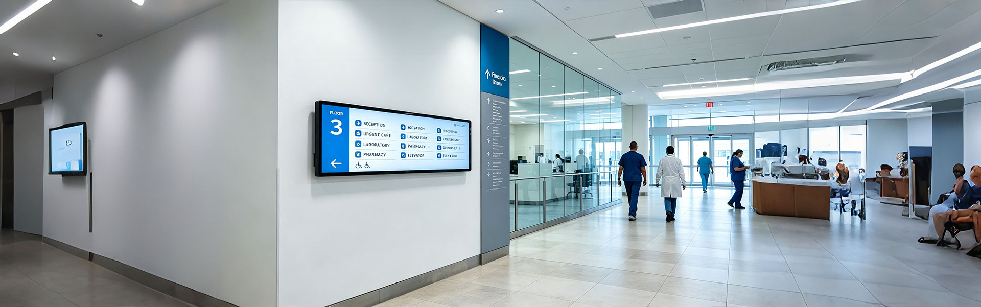
Floor Information Bar LCD Display Solution
Ultra-wide, high-brightness stretched bar LCD disp...
view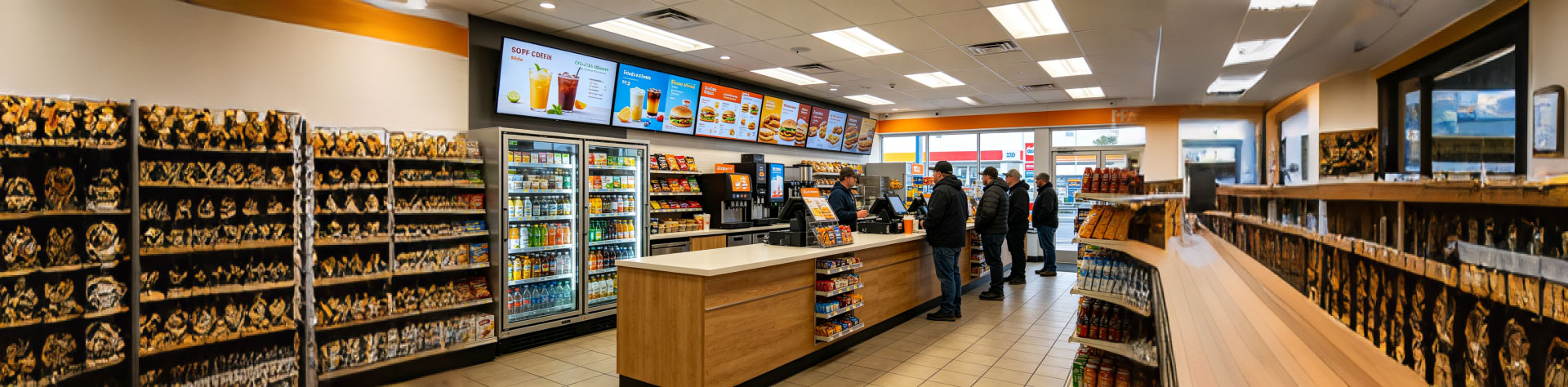
Convenience Store Bar LCD Display Solution
Ultra-slim, high-brightness stretched bar LCD disp...
view
Bus Passenger Information Stretched Bar Display Solution
A rugged, ultra-wide stretched bar display solutio...
viewRelated Products
You may also be interested in the following products