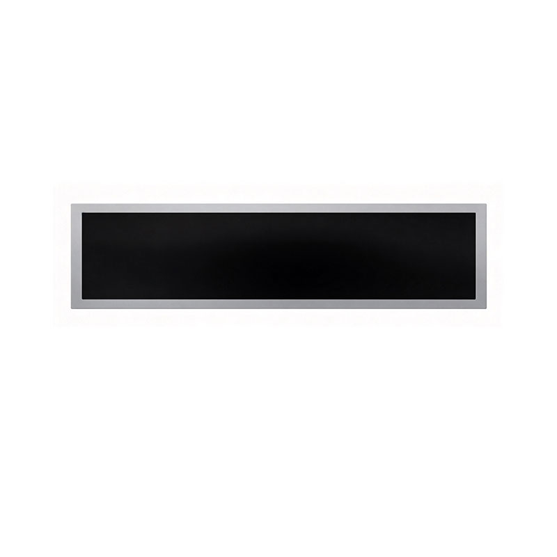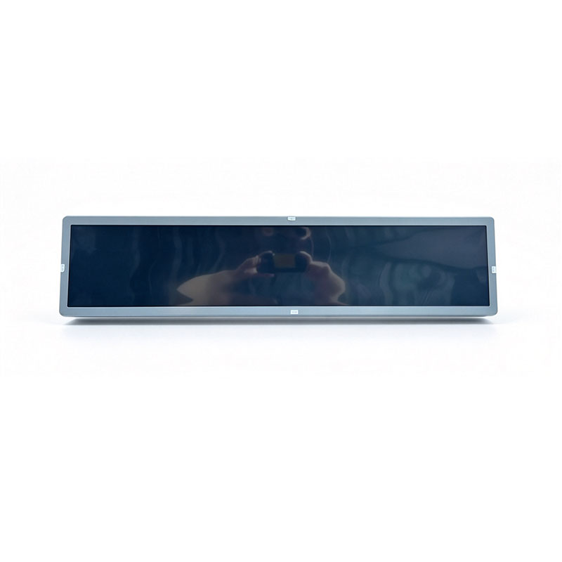
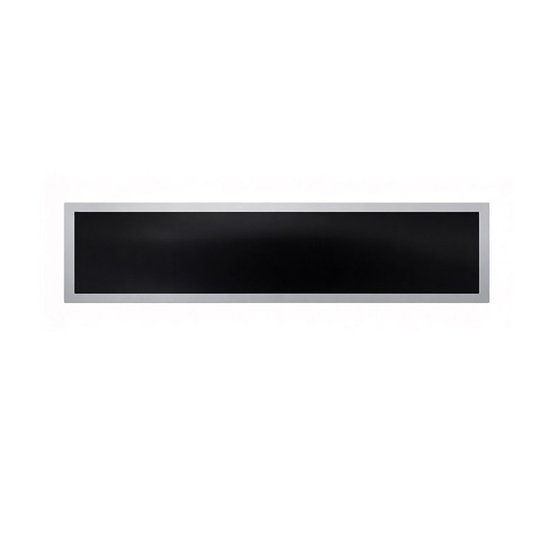
27.8 Inch Cuttable Stretched TFT LCD Module1920×270,
MODEL: HT278HBM
Need customized solution?
Our engineering team is always ready to provide you with professional technical support and flexible customized services.
Understand light customization servicesBuilt by us. Configured for you.
HITULCD supplies LCD modules and display solutions directly from our manufacturing operation, giving OEMs, integrators and distributors direct access to engineering, customization and production.
Supply
Supplier Qualification
VerificationTechnical Specifications
| LCD PANEL PARAMETERS | HDMI/CONTROL BOARD SPECIFICATIONS | ||
|---|---|---|---|
| ITEM | DETAILS | ITEM | DETAILS |
| Model Number | HT278HBM | Input Interface | Require LVDS Driver Board (51‑pin) |
| Manufacturer | HITULCD | Power Input | DC 12V‑4A |
| Diagonal Size | 27.8" Cut‑Type Stretched Bar (32" panel 1/4 cut, Not Native Panel) | OSD KEYS | Depends on LVDS controller |
| Resolution | 1920(RGB) × 270, >3:1 | OSD CONTROL | Depends on LVDS controller |
| Panel Type | a‑Si TFT‑LCD, LCM | ||
| Pixel Arrangement | RGB Vertical Stripe | ||
| Display Area(A.A) | 698.4(W)×98.2(H) mm | ||
| Overall Dimension | 728.4(W)×128.2(H)×20(D) mm(Max.thickness) | ||
| Panel Weight | - | ||
| Surface Treatment | Transmissive polarizer,Parameter not published | ||
| Contrast Ratio | - (Not published) | ||
| Typical Brightness | 500 NITS (Customizable: 300~1000 NITS) | ||
| Response Time | - (Not published) | ||
| LCD Technology | IPS, Normally Black, Transmissive | ||
| Viewing Angle | 89°/89°/89°/89°(Typ.) | ||
| Viewing Direction | Full Viewing Angle | ||
| Display Colors | 16.7M Colors | ||
| Refresh Rate | 60Hz (Est.) | ||
| Backlight Type | WLED,Life‑time not published | ||
| Power Consumption | - (Not published) | ||
| Signal Interface | 51 pins,0.5 mm LVDS | ||
| Supply Voltage | 12.0V (Typ.) | ||
| Touch Panel | Without Touch Function | ||
| Application Fields | Industrial Equipment,Digital Signage | ||
| Operating Temperature | 0 ~ 50 °C | ||
| Storage Temperature | -20 ~ 70 °C | ||
| Important Remark | Cut‑type stretched‑bar module (32‑inch TV panel 1/4 cut),not original panel‑vendor native panel.Most optical & electrical parameters are not officially published,please verify by actual sample.Only support 0‑50℃ operating temperature. | ||
OEM / ODM Custom-Cut Bar LCD Solutions – Any Size, Any Aspect Ratio
Your enclosure sets the dimension. We cut the display to fit.
From 18.5" to 55" source panels, HituLCD engineers custom bar-type and stretched TFT-LCD modules to the exact length, height and aspect ratio your product needs – with validated edge sealing, matched driver electronics and production-ready supply.
Custom size · Edge sealing · Driver board & firmware · Housing & branding · 20-pc samples · MOQ 50 pcs
| Start a Free Cutting Feasibility Review | Download OEM/ODM Capability Brochure |
|---|
1. Why Bar Displays Are Going Custom
Standard 16:9 panels rarely fit the places where information is actually needed: shelf rails, bus and metro ceilings, elevator headers, instrument fascias, vending fronts and equipment control strips. Designing around a fixed panel size forces compromises in enclosure design, cost and user experience.
A custom-cut bar display reverses the logic – the display adapts to the product:
Fits the space exactly – no oversized bezels, no wasted enclosure volume
No new glass tooling – lower NRE and faster time-to-market than a fully new-cell design
Lower total cost – one validated platform, many dimensions
Consistent quality – proven TFT-LCD cell, backlight and driver architecture, adapted rather than reinvented
Typical buyers: hardware OEMs, digital-signage brands, retail-technology integrators, transportation system suppliers, industrial-equipment manufacturers and vending / kiosk makers in North America, Europe and Asia-Pacific.
2. What We Can Cut – Size Coverage
We work from a broad portfolio of source panels and trim one axis (length or height) to your target dimension. Because the process is engineered per project, we can deliver virtually any bar size and aspect ratio within the physical limits of the source panel – confirmed by a free feasibility review before you commit.
2.1 Source Panel Range
| Source panel | Typical use as a bar platform |
|---|---|
| 18.5" – 23.8" | Compact bars, shelf edge, vehicle and instrument fascias |
| 27" | Mid-size signage strips, elevator and lobby displays |
| 32" | Long transit and retail strips |
| 40" – 55" | Extra-long bars, ceiling and wall-mounted signage |
2.2 Example Bar Formats (16:9 FHD source, cut on the vertical axis)
| Source panel | Source active width | Example cut (H × V) | Approx. bar diagonal | Aspect ratio |
|---|---|---|---|---|
| 21.5" | ≈ 476 mm | 1920 × 270 | ≈ 18.9" | ≈ 7.1 : 1 |
| 23.8" | ≈ 527 mm | 1920 × 360 | ≈ 21.1" | ≈ 5.3 : 1 |
| 27" | ≈ 598 mm | 1920 × 270 | ≈ 23.8" | ≈ 7.1 : 1 |
| 27" | ≈ 598 mm | 1920 × 540 | ≈ 24.4" | ≈ 3.6 : 1 |
| 32" | ≈ 708 mm | 1920 × 270 | ≈ 28.2" | ≈ 7.1 : 1 |
| 40" | ≈ 886 mm | 1920 × 360 | ≈ 35.5" | ≈ 5.3 : 1 |
These are reference examples. Any intermediate dimension can be evaluated – send us your drawing.
2.3 Design Limits (Confirmed in Feasibility Review)
Cut axis: normally the axis away from the source-driver edge, so the array circuitry stays untouched
Minimum remaining height / length: set by gate-driver area, seal width and backlight structure – typically evaluated per project
Aspect ratio: up to approximately 12 : 1* depending on source panel
Tolerance: ±0.2 mm (mechanical) / ±0.1 mm (ultrafast laser)*
3. OEM vs. ODM – Choose Your Level of Engagement
| OEM – Build to Your Spec | ODM – We Design It With You | |
|---|---|---|
| You provide | Drawings, specifications, target volume | Application requirements, environment, budget |
| We provide | Custom cutting, sealing, assembly, testing, private-label packaging | Full concept-to-production: cutting plan, optical design, electronics, housing, firmware, certification support |
| Best for | Brands with an in-house mechanical / electronics team | Companies that need a turnkey display subsystem |
| Typical deliverables | Cut & sealed LCD module (with or without driver board) | Complete display assembly, ready to install |
| IP & branding | Your brand, your part number, your packaging | Custom design, NDA-protected, your IP ownership |
4. What We Customize
4.1 Mechanical & Cutting
Length / height / aspect ratio
Cut-edge position and tail (FPC / COF) orientation
Backlight frame, bezel, brackets, VESA and rail mounts
Open-frame, sheet-metal or aluminum housings
4.2 Optical
Brightness: 300 – 1,000 nits standard; 2,000+ nits direct-lit series for direct-sunlight applications
Surface: anti-glare, anti-reflective, anti-fingerprint
Optical bonding (OCA / LOCA) and cover glass
Viewing angle: IPS / wide-view options
4.3 Electrical & Interface
LVDS, HDMI, eDP, VGA, MIPI* and custom PCBA
Resolution and timing adaptation for the cut format
PWM / DC dimming, ambient-light sensor, OSD
Wide-voltage input (9–36 V DC*), PoE and power-sequencing options
4.4 Touch & System Integration
Custom-size PCAP touch sensor (cut-to-fit) with optical bonding
Embedded Android / Linux media-player boards, 4G / Wi-Fi / Ethernet
Remote content management (CMS) integration support
4.5 Branding & Packaging
Private-label / logo printing, custom part numbers
ESD-safe packaging, custom cartons, pallets and labeling
Region-specific documentation (RoHS, REACH, CE / FCC support)
5. Our Custom Cutting Process
Step 1 – Requirement & Drawing ReviewShare your target size, tolerance, interface and environment. We respond within 24 hours.
Step 2 – Feasibility & DFM Report (within 3 working days)Circuit-avoidance check (Gate / Source routing, TFT array, seal line), recommended cutting method, drawing proposal and risk list.
Step 3 – Engineering Samples (20 pcs)Cut, sealed, assembled and tested. Typical lead time: 3–4 weeks after drawing sign-off*.
Step 4 – ValidationYour team evaluates the samples; we provide optical, electrical and reliability data (see Section 6).
Step 5 – Pilot Run100–200 pcs to verify yield, assembly and logistics*.
Step 6 – Mass ProductionControlled process, 100% edge and optical inspection, outgoing quality report.
Step 7 – Lifecycle SupportPCN change control, long-term supply planning, RMA and failure-analysis support.
6. Engineering Capability & Quality Assurance
6.1 Cutting Technology
| Method | Best for | Typical capability* |
|---|---|---|
| Mechanical scribe-and-break (diamond wheel) | Standard tolerance, cost-optimized volume | ±0.2 mm, edge chip ≤ 0.2 mm |
| Ultrafast (picosecond) laser | Tight tolerance, minimal chipping, special contours | ±0.1 mm, edge chip ≤ 0.05 mm |
We recommend the method that fits your tolerance, cost and volume – not the one that is simplest for us.
6.2 Edge Sealing & Protection
UV-curable, low-moisture-permeability secondary seal applied by precision dispensing
Optional polarizer edge wrap and moisture-barrier tape
Black light-shielding edge treatment to control light leakage and edge mura
100% microscopic edge inspection; lot-level leak and bake sampling
6.3 Reliability Baseline*
| Test | Condition |
|---|---|
| High / low-temperature storage | 80 °C / −30 °C, 240 h |
| High / low-temperature operation | Per grade (0–50 °C standard, −20–70 °C wide-temp) |
| Damp heat | 60 °C / 90% RH, 240 h |
| High-humidity ("double 85") | 85 °C / 85% RH, 500 h (on request) |
| Thermal shock | −30 ↔ 80 °C, 100 cycles |
| Vibration / shock | 1.5 Grms 5–500 Hz / 50 G 11 ms |
| Packaged drop | ISTA-2A |
Test plans are aligned to your target standard (consumer, industrial, transportation). Benchmark data from comparable cut projects is available under NDA.
6.4 Quality System
ISO 9001-certified manufacturing*, incoming panel inspection, in-process AOI, dark-room mura inspection, full traceability by lot and serial number, 8D failure analysis.
7. Industry Solutions
| Industry | Typical cut-to-fit application |
|---|---|
| Retail | Shelf-edge and gondola-rail displays, promotional strips, cold-chain displays |
| Transportation | Bus, metro, train and airport information strips |
| Industrial | Machine control-panel strips, test instruments, HMIs |
| Vending & Kiosk | Slim front-panel displays, product-selection strips |
| Automotive & Specialty | Dashboard extensions, fleet and emergency-vehicle displays |
| Smart Building | Elevator headers, room-booking bars, wall-mounted information strips |
| Hospitality & Signage | Shop windows, menu boards, ceiling-hung digital signage |
8. Commercial Terms
| Item | Typical terms* |
|---|---|
| NRE / engineering fee | Project-based; typically USD 1,500 – 4,000, refundable or waived when agreed volume is reached |
| Engineering samples | 20 pcs, 3–4 weeks after drawing approval |
| MOQ (custom-cut) | 50 pcs |
| Mass-production lead time | 4–6 weeks ARO |
| Yield target | Cut & seal process ≥ 95%; outgoing quality ≥ 98% after 100% inspection |
| Warranty | 12 months (extended terms on agreement) |
| Supply commitment | 5-year lifecycle target, 6-month EOL notice |
| Incoterms / payment | EXW / FOB / CIF / DDP; T/T, L/C |
| IP protection | NDA and exclusive-design agreements available |
9. Why Work With HituLCD
Cutting + electronics + mechanics in one team – one point of responsibility from glass to finished assembly
Engineering first – every project starts with a feasibility report, not a guess
Low barrier to start – 20-pc samples, 50-pc MOQ, no new glass tooling
Transparent quality – data-driven reliability, traceability, PCN discipline
Export-ready – documentation, labeling and logistics for the EU, UK and North America
Responsive – engineering reply within 24 hours
10. Frequently Asked Questions
Can you really cut to any size?We can cut one axis of a suitable source panel to virtually any dimension, subject to the panel's physical structure (driver area, seal width, backlight). Send us your target and we will confirm feasibility, recommended method and risks – free of charge.
Do I need to buy new glass tooling?No. Custom cuts use existing source panels, which keeps NRE low and shortens lead time.
Is a cut display as reliable as a standard panel?With validated cutting, secondary edge sealing and 100% inspection, cut modules are tested against the same baseline as standard products. We share benchmark data on request.
Will there be light leakage or mura at the cut edge?Edge light-shielding, backlight-frame alignment and dark-room inspection against an agreed limit sample control these risks.
Can you supply the driver board, housing and touch?Yes. ODM projects can include the driver board, firmware, housing, bonding and touch – delivered as a ready-to-install assembly.
What is the smallest order you accept?20 pcs for engineering samples, 50 pcs for custom-cut mass production.
Can you protect our design?Yes. We sign NDAs and can agree exclusivity for custom dimensions and part numbers.
RFQ Checklist
Send the following to receive a quotation and a free feasibility report:
[ ] Target dimension (L × H) and tolerance
[ ] Mechanical drawing (STEP / DXF / PDF) or enclosure sketch
[ ] Brightness, surface treatment, bonding / touch requirement
[ ] Interface (LVDS / HDMI / eDP) and power input
[ ] Operating environment (indoor / semi-outdoor / vehicle / industrial) and target test standards
[ ] Annual volume, target price and project timeline
📧 Email: sales@hitulcd.com⏱ Response time: within 24 hours (Mon–Fri)
Specifications and capabilities are subject to change without notice. Final parameters are defined by the approved specification and drawing. All trademarks belong to their respective owners.
27.8" Cuttable Stretched Bar TFT LCD Module – 1920 × 270, High-Brightness, LVDS
An ultra-wide 7.1:1 bar display that can be trimmed to your exact enclosure dimension – without tooling a new glass size.
Designed for OEM engineers and system integrators who need a non-standard form factor with industrial-grade stability: shelf-edge signage, transit information, industrial control panels, vehicle and machine-mounted HMIs.
MOQ 50 pcs · Custom cutting & edge sealing · 500–1,000 nits · LVDS / HDMI / eDP options · 20-pc engineering samples
| Request a Quote & Cutting Feasibility Review | Download Datasheet & 2D Drawing |
|---|
1. Product Overview
The 27.8" 1920 × 270 stretched TFT LCD module is a bar-type display built on a high-resolution IPS-type TFT-LCD cell with an edge-lit LED backlight. Its 7.1:1 aspect ratio fits spaces that a conventional 16:9 panel cannot – shelf rails, ceiling-mounted passenger information strips, instrument-cluster extensions and slim equipment fascias.
Its cuttable design allows one axis to be trimmed to a non-standard length during OEM integration, so the display matches your mechanical envelope precisely. Every custom cut is preceded by an engineering feasibility review (see Section 5) and finished with a secondary edge seal to protect the cell against moisture and liquid-crystal leakage.
Key Features
Ultra-wide 1920 × 270 resolution – Full-HD width with a 7.1:1 aspect ratio; sharp text, tickers and graphics at 0.364 mm pixel pitch
Cuttable on one axis – Custom length/height without new glass tooling; ideal for fixed enclosure sizes
High brightness 500–1,000 cd/m² – Sunlight-tolerant for shop windows, covered transit stations and bright indoor spaces
Wide viewing angle IPS-type* – 178°/178° (typ.), stable colors for wall-, ceiling- or shelf-mounted installations
Industrial interfaces – LVDS (native); HDMI, VGA or eDP via matching driver board
Long backlight life – 50,000 h (typ.*) LED backlight, brightness adjustable by PWM
Extended temperature option – Standard 0 to 50 °C; wide-temperature version −20 to 70 °C*
Engineered edge protection – UV-cured secondary sealing, light-shielding edge treatment, 100% edge inspection
Long-term supply – 5-year availability target* with change-notification (PCN) policy
2. Technical Specifications
2.1 General & Optical
| Parameter | Specification |
|---|---|
| Display type | TFT-LCD, transmissive, IPS-type* (normally black) |
| Diagonal size | 27.8 inch (706 mm) |
| Resolution | 1920 (H) × 270 (V) pixels |
| Aspect ratio | ≈ 7.1 : 1 |
| Active area | 699.2 (W) × 98.3 (H) mm |
| Pixel pitch | 0.364 × 0.364 mm |
| Pixel arrangement | RGB vertical stripe |
| Color depth | 16.7 M colors (8-bit) |
| Color gamut | 72% NTSC (typ.)* |
| Brightness | 500 cd/m² (standard) / 1,000 cd/m² (high-brightness), typ. |
| Contrast ratio | 1,000 : 1 (typ.)* |
| Viewing angle (L/R/U/D) | 89° / 89° / 89° / 89° (typ.), CR ≥ 10* |
| Response time | 14 ms (typ., Tr + Tf)* |
| Brightness uniformity | ≥ 75% (9-point)* |
| Surface treatment | Anti-glare (haze 25%*), hardness 3H*; AR / AF / optical bonding on request |
2.2 Electrical
| Parameter | Specification |
|---|---|
| Signal interface | LVDS, 1-ch, 8-bit, 30-pin* (native) |
| Optional interfaces | HDMI / VGA / eDP via driver board; USB-C or custom PCBA on request |
| Refresh rate | 60 Hz |
| Logic supply voltage | 3.3 V DC (typ.) |
| Backlight | Edge-lit white LED |
| Backlight dimming | PWM, 200 Hz – 1 kHz*, 1–100% |
| Backlight lifetime | 50,000 h (typ., @25 °C, to 50% initial brightness)* |
| Power consumption | ≈ 8 W @ 500 nits · ≈ 15 W @ 1,000 nits (typ.)* |
| Driver board input | 12 V DC ± 5% (typ.)* |
2.3 Mechanical
| Parameter | Specification |
|---|---|
| Module outline (W × H × T) | ≈ 712 × 112 × 12.5 mm (typ.; final per approved drawing)* |
| Weight | ≈ 1.3 kg (typ.)* |
| Cutting axis | One axis (length or height) – per feasibility review |
| Cutting tolerance | ±0.2 mm (mechanical) / ±0.1 mm (laser)* |
| Mounting | Chassis with M3 threaded inserts; open-frame or bezel options |
| Tail / connector orientation | Customizable to match your enclosure |
2.4 Environmental
| Parameter | Standard | Wide-temp option* |
|---|---|---|
| Operating temperature | 0 to 50 °C | −20 to 70 °C |
| Storage temperature | −20 to 60 °C | −30 to 80 °C |
| Operating humidity | 10–90% RH, non-condensing | 10–90% RH, non-condensing |
| Ingress protection | Module level (IP rating determined by enclosure / bonding) | — |
2.5 Compliance
RoHS 2.0 and REACH compliant materials. CE / FCC / UKCA certification is performed at system level; we provide the documentation and EMC pre-test support for the driver board. UL/IEC 62368-1 reports available on request.
3. Reliability & Edge-Sealing Assurance
Cutting the display is only valuable if the cut edge is as dependable as an uncut panel. Our process is validated around four risks: moisture ingress, liquid-crystal leakage, edge cracking and optical defects.
3.1 Secondary Edge Sealing
Sealing method: After cutting, the exposed cell edge is sealed with a UV-curable, low-moisture-permeability epoxy/acrylic sealant applied by precision dispensing, followed by UV + thermal post-cure.
Moisture barrier: Optional polarizer edge wrap and barrier tape for humid or condensing-prone applications.
Leak inspection: 100% visual inspection under magnification, plus sample vacuum / pressure-bake checks per lot.
3.2 Environmental Test Baseline
Typical test conditions applied to cut modules (samples per project; full reports available under NDA):
| Test | Condition | Pass criteria |
|---|---|---|
| High-temperature storage | 80 °C, 240 h* | No functional or cosmetic degradation |
| Low-temperature storage | −30 °C, 240 h* | Same |
| High-temperature operation | 50 °C (70 °C wide-temp*), 240 h | Same |
| Low-temperature operation | 0 °C (−20 °C wide-temp*), 240 h | Same |
| Damp heat | 60 °C / 90% RH, 240 h* | No edge delamination, no liquid-crystal bubbles |
| "Double 85" high-humidity test | 85 °C / 85% RH, 500 h (available on request)* | No leakage, no edge corrosion, no mura growth |
| Thermal shock | −30 ↔ 80 °C, 30 min dwell, 100 cycles* | No cracks, no seal opening |
| Vibration | 1.5 Grms, 5–500 Hz, 3 axes, 1 h/axis* | No damage / no display defect |
| Mechanical shock | 50 G, 11 ms, half-sine* | No damage / no display defect |
| Packaged drop | ISTA-2A / 76 cm, 10 drops* | No damage |
Tip for buyers: State your target standard (consumer, industrial, transportation, etc.) in the RFQ. We will align the test plan and share benchmark data from comparable cut projects.
3.3 Optical Quality After Cutting
Light leakage: Black light-shielding edge coating/tape and backlight-frame alignment control the edge glow.
Color shift & mura: 100% dark-room inspection at L0, L127 and white patterns; edge-zone mura is evaluated against an agreed limit sample.
Brightness uniformity: Verified on the cut module (9-point) and recorded in the outgoing report.
4. Interface & Integration Options
| Option | Description |
|---|---|
| LVDS direct | Native interface; ideal for embedded boards and industrial SBCs |
| HDMI driver board | Plug-and-play with media players; includes OSD, audio out on request |
| eDP / VGA | Available for specific host platforms |
| Touch (PCAP) | Custom cut-to-fit PCAP sensor with optical bonding (OCA/LOCA), USB / I²C |
| Optical bonding | Improves sunlight readability, condensation and vibration resistance |
| Custom housing & brackets | Sheet-metal or aluminum housing, VESA / rail-mount, ODM branding, private-label packaging |
| Embedded controller | Android / Linux player board, 4G/Wi-Fi, PoE options on request |
5. Custom Cutting & Engineering Support
5.1 Cutting Methods
| Method | Best for | Typical capability* |
|---|---|---|
| Mechanical (diamond wheel scribe & break) | Standard tolerances, cost-optimized mass production | ±0.2 mm; edge chip ≤ 0.2 mm |
| Ultrafast (picosecond) laser cutting | Tight tolerances, minimal chipping, complex contours | ±0.1 mm; edge chip ≤ 0.05 mm |
The method is recommended per project after our engineers review dimensions, tolerance requirements and the location of the array area.
5.2 Feasibility Review – What We Check
Routing & circuit avoidance: The cut line is validated against the Gate/Source fan-out, GOA/TFT array area, seal line and COF/bonding area to ensure no active circuit is affected.
Edge quality: Edge straightness, chipping and micro-crack control are inspected by microscope; cracks extending into the seal or active area are rejected.
Timing & driver adaptation: Timing controller and firmware are adapted to the new resolution / active area.
Mechanical fit: Bezel, backlight frame, tail routing and tolerance stack-up are checked against your enclosure.
5.3 What We Need From You (for Feasibility Confirmation)
Target cut dimension and tolerance
Enclosure / mechanical drawing (STEP or DXF/DWG preferred)
Interface, brightness and operating-temperature requirements
Application environment (indoor / semi-outdoor / vehicle / industrial) and target test standards
Estimated annual volume and project schedule
Within 3 working days, we return a feasibility report with recommended cutting method, drawing proposal and risk points.
6. Commercial Terms: NRE, Samples, MOQ & Lead Time
| Item | Typical terms* |
|---|---|
| NRE / engineering fee | Project-based; typically USD 1,500 – 4,000 covering fixture, cutting program and drawing. Refundable / waived when the agreed volume is reached |
| Engineering samples | 20 pcs, ready in 3–4 weeks after drawing sign-off |
| Pilot run | 100–200 pcs, 4–6 weeks |
| Mass-production MOQ | 50 pcs (custom-cut) |
| Mass-production lead time | 4–6 weeks ARO |
| Expected yield | Cut & seal process yield ≥ 95% target; ≥ 98% outgoing quality after 100% inspection (AQL 0.65 major)* |
| Warranty | 12 months (24 months available with agreement) |
| Lifecycle | 5-year supply target; 6-month EOL notice |
| Incoterms | EXW / FOB Shenzhen / CIF / DDP (selected destinations) |
| Payment | T/T, PayPal for samples, L/C for large orders |
| Packaging | ESD antistatic packaging, custom cartons and pallets, private-label options |
7. Typical Applications
Retail: Shelf-edge electronic labels, supermarket rail displays, price and promotion strips
Transportation: Bus, metro and train passenger information strips, station and platform signs
Industrial equipment: Control-panel extensions, machine-mounted HMIs, test and measurement instruments
Vehicle & specialty: Dashboards, ambulance / fleet displays, kiosks and vending machines
Commercial signage: Shop windows, elevator and lobby strips, ceiling-hung digital signage
Smart building: Room-booking strips, control panels, wall-mounted informational bars
8. Frequently Asked Questions
Can the display be cut to any length?Within the limits confirmed in the feasibility review. The cut axis, minimum remaining size and driver location determine the possible dimension.
Will cutting affect reliability?When cut and sealed according to our validated process, cut modules are tested against the same baseline as standard products (see Section 3). We share test data from comparable projects on request.
Which cutting method do you recommend?Mechanical cutting is usually the cost-optimized choice for ±0.2 mm tolerances; ultrafast laser is recommended for tight tolerances and minimal chipping. The final choice is made after DFM.
Is the display suitable for direct sunlight?The 1,000-nit version suits covered transit stations, shop windows and bright interiors. For direct-sunlight outdoor use, we recommend our 2,000+ nits series with optical bonding.
Can you provide a custom controller / housing?Yes. We offer OEM/ODM services: custom brightness, interface, driver board, housing, logo branding and private-label packaging.
Do you support small volumes?Yes. Engineering samples start at 20 pcs and custom-cut mass production at 50 pcs.
RFQ Checklist
To receive an accurate quotation and feasibility report, please send:
[ ] Required size / cut dimension and tolerance
[ ] Brightness (500 / 1,000 nits) and surface treatment
[ ] Interface (LVDS / HDMI / eDP) and touch requirements
[ ] Operating environment and target test standards
[ ] Annual volume and target price
[ ] Mechanical drawing (STEP / DXF / PDF)
📧 Email: sales@hitulcd.com💬 Response time: within 24 hours (Mon–Fri)
Contact Our Engineering Team →
Specifications are subject to change without prior notice. Final parameters are defined by the approved product specification and 2D drawing. All trademarks belong to their respective owners.
Know The Terms Before You Inquire.
|
01 — Shipping Terms
Incoterms Available
EXW
Ex Works — pick up from our factory
FOB
Free On Board — most common for ocean freight
CIF
Cost, Insurance & Freight — to your port
|
02 — Order Minimum
MOQ: 1 Units
Applies to standard specs. Custom brightness, cutting or bezel may adjust MOQ, confirmed at quotation. Sample units available before bulk order
|
03 — Payment Protection
Multiple Secured Methods
|
A Real Factory. Publicly Verifiable.
|
Legal Company Name
Shenzhen Hantu Jiashi Technology Co., Ltd.
|
Unified Social Credit Code
91440300306068446B
|
|
Legal Representative
YUN CHEN
|
Registered Capital
RMB 2,000,000
|
|
Established
May 23, 2014 (11+ years operation)
|
Business Status
● Active / In Operation
|
|
Registered Factory Address
Building B, Gangshen Innovation Park, Huaning Road, Dalang Sub-district, Longhua District, Shenzhen, Guangdong, China
|
|
Contact HITULCD
We'll respond via email within 24 hours. If you'd like to discuss details over WhatsApp or a call, please leave a preferred time and contact method in your message — we will never call you unannounced.
Related solutions
This product is suitable for the following industry application scenarios
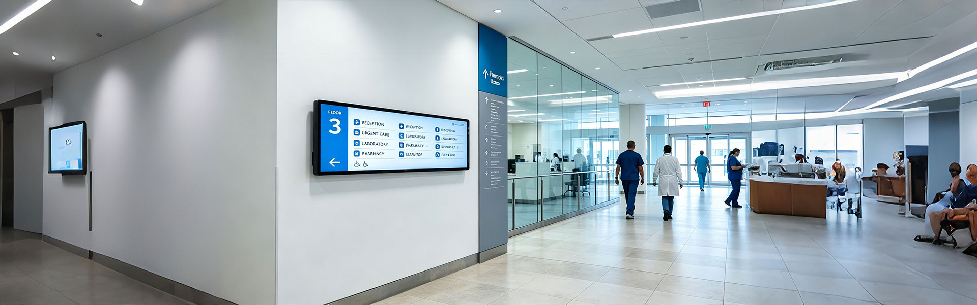
Floor Information Bar LCD Display Solution
Ultra-wide, high-brightness stretched bar LCD disp...
view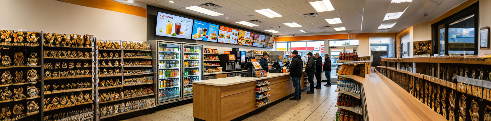
Convenience Store Bar LCD Display Solution
Ultra-slim, high-brightness stretched bar LCD disp...
view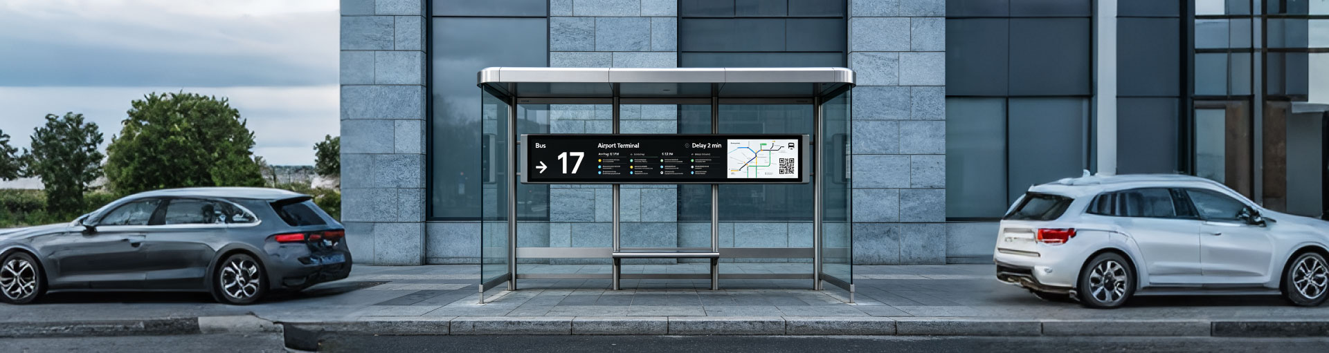
Bus Passenger Information Stretched Bar Display Solution
A rugged, ultra-wide stretched bar display solutio...
viewRelated Products
You may also be interested in the following products