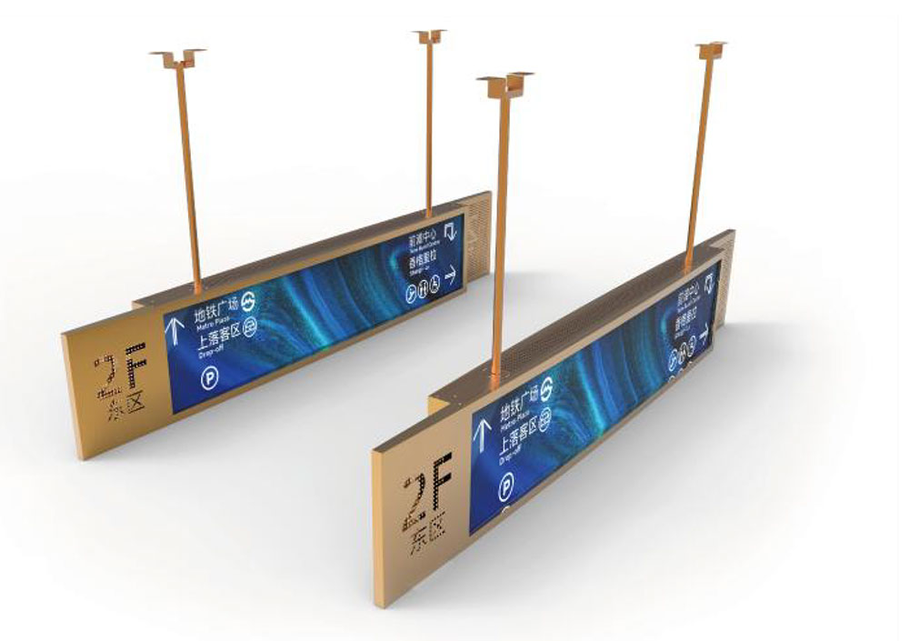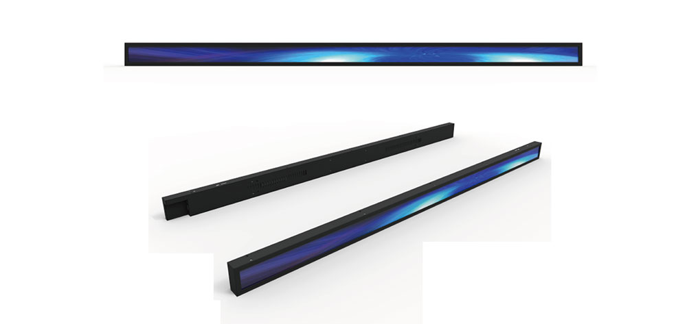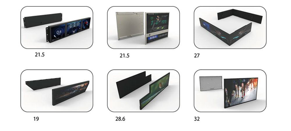
A bar LCD module — the stretched-format panel found in shelf-edge labels, vehicle instrument clusters, kiosk headers, transit signage and rack-mount status strips — looks like an ordinary TFT that someone squeezed. In practice, almost every electrical decision that works well on a 16:9 panel becomes a compromise once the aspect ratio stretches past 3:1. The glass is long and narrow, the bezel is thin on at least two sides, the FPC has to exit through a gap of a few millimetres, and the timing controller has to be programmed with a resolution that no VESA standard ever defined. This paper walks through the three customization levers that determine whether a bar module integrates cleanly or fights the enclosure: the flexible printed circuit, the connector interface, and the controller architecture.

1. Why the Bar Format Changes the Electrical Design
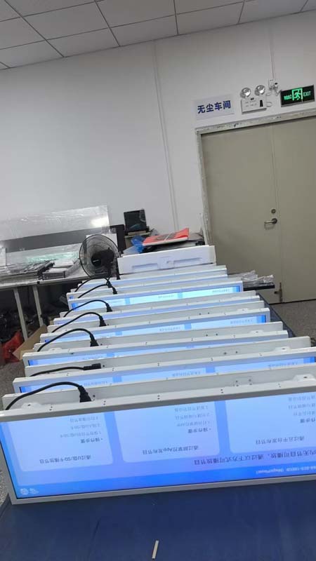
A 1920 × 540 module at 60 Hz carries roughly 62 million pixels per second — about a third of a full-HD panel — yet it can be 500 mm wide. Three consequences follow immediately.
- Routing length dominates. The gate lines run the short dimension, the source lines run the long one. Source drivers are therefore distributed along the long edge, and the FPC that feeds them has to span a much greater physical distance than on a conventional panel.
- Pixel clock sits in an awkward band. 1920 × 540 at 60 Hz lands near 75–80 MHz once blanking is included. That is just under the 85 MHz practical ceiling of a single-channel LVDS link, which makes LVDS technically viable but with almost no margin for spread-spectrum modulation or cable loss.
- Standard timings do not exist. There is no CEA or VESA timing entry for most bar resolutions. Either the timing controller is programmed with a custom parameter set, or the host SoC must be able to output a fully custom mode — a constraint that eliminates many off-the-shelf bridge chips.
2. FPC Options: The Most Under-Specified Part of the Module
The flexible circuit is where most field failures originate, and it is the component most often chosen by habit rather than analysis. Five parameters deserve explicit specification.
2.1 Layer count and material stack
Single-sided FPCs are adequate for panels up to roughly 40 pins with no differential pairs. Once MIPI D-PHY lanes or LVDS pairs are present, a two-layer construction with a continuous ground plane is effectively mandatory: the reference plane is what makes 100 Ω differential impedance achievable and repeatable. For 4-lane MIPI at 1.5 Gb/s per lane, specify a two-layer FCCL with 1/2 oz copper, a 25 µm polyimide coverlay, and impedance coupons on the production panel so the fabricator can verify the stack rather than estimate it.
2.2 Length, bend radius and mechanical relief
Static bend radius should be no tighter than 20× the FPC thickness; dynamic or repeated-motion applications need 100× or more, or a different solution entirely. A 0.3 mm FPC with stiffener therefore needs roughly a 6 mm minimum static bend radius, which is often larger than the gap behind a slim bezel. When the geometry cannot be satisfied, the correct answer is usually an articulated path with a fold-and-crease defined in the drawing, plus a mechanical bracket that carries the load — never letting the FPC itself locate the panel.
2.3 Shielding and EMI
Bar modules are frequently installed against a metal chassis with a switching backlight driver a few millimetres away. Silver-ink or copper-mesh shielding layers on the FPC, terminated to ground through multiple vias rather than a single tab, reduce both radiated emissions and the risk of the backlight PWM coupling into the D-PHY lanes. If the module carries a radio or a capacitive touch sensor nearby, add a grounded shield layer and specify the ground stitching pattern in the drawing.
2.4 Stiffeners and contact finish
ZIF contacts need a stiffener of 0.2–0.3 mm behind the gold fingers to guarantee insertion force and prevent delamination. Specify hard gold plating of at least 0.3 µm over 1–2 µm nickel for connectors rated above 20 mating cycles; thinner flash gold will wear through during rework. For permanently mated designs, a solder tab or hot-bar land is more reliable than a connector.
2.5 ESD and protection
Place TVS diodes or an ESD array as close to the connector as the layout allows, especially on the MIPI or LVDS pairs and on the reset and standby lines. Bar modules are often serviced in the field with the panel still mounted, and a finger discharge into an exposed FPC tail is a realistic event.
3. Connector Options
There is no single correct connector; the right choice depends on mating cycles, serviceability, panel thickness and vibration exposure.
| Connector type | Typical pitch | Mating cycles | Best fit | Watch-outs |
|---|---|---|---|---|
| ZIF FPC (front-flip or back-flip) | 0.5 mm / 0.3 mm | 20–30 | General-purpose modules, serviceable | Requires stiffener; flip direction must match FPC exit |
| Non-ZIF FPC (direct insertion) | 0.5 mm / 1.0 mm | 10–20 | Cost-sensitive, low-mating designs | Higher insertion force; contact wear on rework |
| Board-to-board (BTB) | 0.35–0.5 mm | 30–50 | Vibration, automotive clusters | Adds mated height; needs locating bosses |
| Hot-bar / ACF direct bond | n/a | Permanent | Harsh environment, sealed enclosures | Not serviceable; reflow profile must be controlled |
| Separate backlight connector | 1.0–1.5 mm | 10–30 | High-current LED strings, dual-string with NTC | Keep away from signal FPC to limit PWM coupling |
Three rules of thumb are worth carrying into every bar-module design review. First, keep the signal FPC and the backlight harness physically separated by at least the width of the connector body; a 20 kHz PWM return current running parallel to a D-PHY pair will show up as periodic jitter. Second, on long, thin modules, place the connector near the centre of the long edge rather than at one end — this halves the maximum FPC run and reduces skew between the first and last source driver. Third, if the enclosure is assembled and disassembled in the factory more than a handful of times, budget for a BTB connector even though it costs more; worn ZIF actuators are a documented yield killer.
4. Controller and Interface Options
The controller choice determines the host-side bill of materials, the cable length budget and the achievable refresh rate. Four architectures are common in bar modules.
4.1 Integrated TCON with LVDS input
The lowest-risk option. A single LVDS channel comfortably carries 1920 × 540 at 60 Hz, and LVDS is immune to the lane-swap and polarity mistakes that plague MIPI bring-up. Its limitation is channel bandwidth: at 3840 × 1080 or at 120 Hz refresh, single-channel LVDS runs out of headroom and the design must move to dual-channel LVDS — which doubles the pair count and pushes the FPC to four or six layers.
4.2 MIPI DSI
Two lanes suffice for most bar resolutions at 60 Hz; four lanes are needed for high refresh or 4K-class stretched panels. MIPI has the smallest pin count and the lowest EMI envelope, and it is the natural fit for SoC-based products where the display is driven directly. The trade-offs are real: D-PHY needs controlled 100 Ω differential impedance, lane ordering must be confirmed against the panel's documented mapping rather than assumed, and many low-cost bridge chips simply cannot generate a non-standard resolution such as 2880 × 864.
4.3 eDP
Embedded DisplayPort becomes attractive above roughly 2560 pixels of horizontal resolution and where a single cable must carry both video and auxiliary control. Its main drawback in bar modules is the additional lane count and the stricter board layout discipline it imposes on the FPC.
4.4 RGB parallel and MCU interfaces
Still found in small bar displays under about 8 inches where a low-cost MCU drives the glass directly. For panels wider than roughly 800 pixels the pin count and the slew-rate limits of a parallel RGB bus make this impractical; a bridge to LVDS or MIPI is the better answer.
Beyond the video path, two controller functions deserve early attention. The first is the backlight driver: constant-current boost or buck-boost, with PWM or analogue dim KEYWORDS: Custom FPC, Connector and Controller Options for Bar LCD Modules