The Case for Bar-Format Displays in Vehicle and Wayside Systems
Transportation equipment is an unforgiving host for a display. A panel that performs beautifully in a climate-controlled lobby must survive a bus idling in Death Valley, a tram traversing a rail joint at 60 km/h, a taxi roof sign baking in direct sun, or an EV charging kiosk hit by a pressure washer at 3 a.m. At the same time, the available mounting volume in these machines is rarely a comfortable 16:9 rectangle. It is a strip: above a door, under a luggage rack, between a dashboard cluster and a windshield, or along the top edge of a fare gate.
This mismatch between a rectangular screen and a strip-shaped cavity is why industrial bar LCD displays — also called stretched, ultra-wide, or ribbon displays — have moved from novelty to default specification in modern transportation design. This paper covers what distinguishes a transportation-grade bar display from a generic stretched panel, how to specify one, and where integration projects typically go wrong.
1. What "Industrial Bar LCD" Actually Means
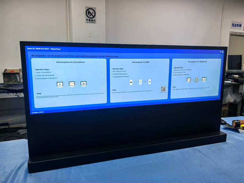
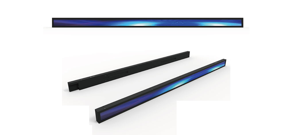
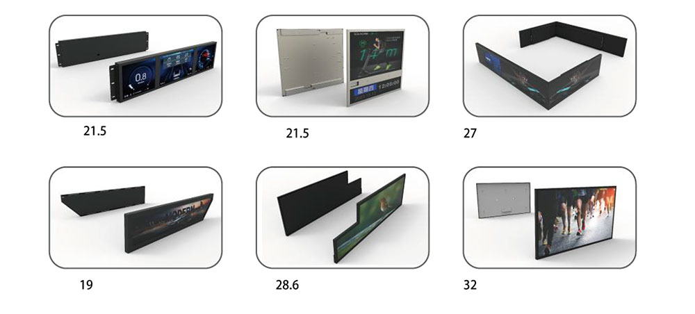
A bar LCD is an active-matrix TFT display cut to an aspect ratio far wider than the consumer mainstream. Where a standard monitor sits at 16:9 (1.78:1), bar panels typically run from 3:1 to 5:1. Common formats include 16:4.5, 16:3.9, 16:3 and 8:3, produced at diagonal sizes that cluster around 19.5", 24.5", 28", 37", 43" and larger.
Three properties separate a true industrial bar panel from a commercial signage strip:
- Thermal headroom. Operating range of −30 °C to +80 °C, with storage to −40 °C, and — critically — no permanent optical degradation after cold-start operation, which is where cheaper panels develop mura and edge shadowing.
- Optical output matched to ambient light, not to a dark room. 1,000–2,000 cd/m² typical, with the higher end reserved for forward-facing vehicle positions and outdoor kiosks.
- Qualification to a transport standard, not a datasheet hand-wave. Shock, vibration, EMC and fire-performance evidence that a systems integrator can file with a rail authority or vehicle OEM.
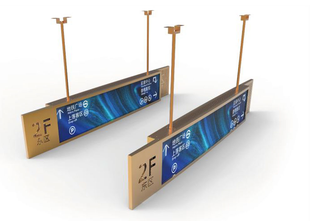
Bar panels are also attractive because they replace legacy technology. A dot-matrix LED sign, an electromechanical flap indicator or a scrolling LED text bar can be swapped for a bar LCD that reproduces the same footprint while adding full-colour graphics, multiple languages, accessibility icons and dynamic route data from the vehicle's information backbone.
2. Where Bar Displays Fit in a Vehicle Architecture
Design intent varies sharply by position, and the optical specification must follow the position rather than the other way around.
| Integration Point | Typical Size | Brightness | Design Priority |
|---|---|---|---|
| Rail / tram passenger information strip (above door, ceiling) | 28"–43" | 500–1,000 cd/m² | Uniformity, wide viewing angle, EN 45545 fire performance |
| Bus interior route and next-stop bar | 24"–37" | 700–1,200 cd/m² | Reflection control under fluorescent and LED cabin lighting |
| Taxi roof sign / rideshare identifier | 16"–28" | 1,500–2,500 cd/m² | Direct-sun legibility, IP65+, vandal resistance |
| EV charger and parking-gate strip | 19.5"–28" | 1,000–1,500 cd/m² | UV stability, condensation resistance, 24/7 duty |
| Driver console / dashboard secondary strip | 8"–19.5" | 800–1,200 cd/m² | Low reflectivity, dimming to < 1 cd/m² for night operation |
| Wayside platform and depot signage | 37"–58" | 1,500–2,500 cd/m² | Heater for cold climates, long MTBF |
Note the tension in that table: the same product family must dim to below 1 cd/m² at night and still read at 100,000 lux in daylight. A panel that only specifies peak brightness is underspecified. The useful metric is the dimming ratio — the ratio of maximum to minimum stable luminance — and whether the low end is achieved by backlight current reduction or by PWM so aggressive that it produces visible flicker or beating with dashcam and camera-based ADAS systems.
3. Optical Design: Sunlight Readability Is Not Just Nits
Brightness is necessary but far from sufficient. Perceived legibility in a vehicle is governed by the contrast ratio under ambient illumination, which is dominated by reflected light:
Effective contrast ≈ (L_display + L_reflected) / (L_black + L_reflected)
Once L_reflected exceeds a few hundred cd/m², doubling the backlight buys very little. Practical countermeasures, in order of cost-effectiveness:
- Optical bonding. Filling the air gap between panel and cover glass with an index-matched adhesive eliminates the internal glass/air reflections — typically recovering 60–80% of the contrast lost to surface glare, and simultaneously improving impact resistance and eliminating fogging inside the gap.
- Anti-glare and anti-reflective treatment. AG diffusion for large signage viewed at a distance; AR coating for driver-facing positions where a mirror image of the cabin is unacceptable.
- Circular polariser. Essential if the driver or passengers will wear polarised sunglasses, which otherwise black out a linearly polarised panel at certain head angles.
- Bezel and recess geometry. A shallow hood or recessed mounting does more for daytime contrast than an extra 300 nits.
Also specify uniformity: a bar panel's extreme aspect ratio makes backlight design harder, and a 20% centre-to-edge falloff on a 4:1 strip is immediately visible as a gradient across text.
4. Mechanical and Environmental Engineering
4.1 Vibration and shock
Vehicle-mounted electronics must survive random vibration in the 5–500 Hz band plus repeated mechanical shock from rail joints, potholes and door slams. Two failure modes dominate bar displays specifically:
- Backlight stack fatigue. Light-guide plates and diffuser stacks in long, narrow formats act as cantilevers. Specify retention features that support the stack along its length, not just at the ends.
- FPC and connector fretting. Long, thin flexible circuits carrying LVDS or eDP are vulnerable to resonance. Strain relief, adhesive staking and connector locking are not optional in rail applications.
Appropriate references are IEC 61373 (rail rolling stock equipment, categories 1/2/3) and ISO 16750-3 for road vehicles. Ask for the actual test category and axis, not just a "vibration tested" claim.
4.2 Ingress protection and condensation
IP54 is a reasonable floor for cabin-interior units; IP65 or IP67 is expected for roof signs, exterior kiosks and washdown areas. But sealing creates a second problem: a sealed enclosure that cycles between −20 °C and +60 °C will pump moisture unless the design manages it. Solutions include breathable membrane vents, desiccant or molecular sieve packs sized to the internal volume, and conformal coating on the driver PCB. For wayside installations in cold climates, an integrated heater with a thermostat is often more cost-effective than a wider-temperature panel alone.
4.3 Fire performance
For rail interiors, EN 45545-2 defines hazard levels for the complete assembly — housing, gasket, adhesive, diffuser and cable jacket — not merely the glass. A panel that passes while its mounting frame does not is a certification failure waiting to happen. Collect material declarations from every component supplier early; this is the single most common cause of schedule slip in rail interior display projects.
5. Electrical Integration and Signal Chain
Bar panels rarely come with a convenient HDMI input. Expect one of the following:
- LVDS — mature, robust, well-supported by automotive SoCs, limited by cable length and lane count at high resolution.
- eDP — higher bandwidth, better for 4K-wide strips, but requires attention to differential pair routing and EMI.
- MIPI DSI — common on small bar panels in driver consoles; short-reach only.
- V-by-One HS — used on large-format signage strips, one pair per lane, long cable tolerance.
Three integration details are routinely underestimated:
Cable length and equalisation. A routing run from a controller in the luggage bay to a bar display above a door can easily exceed two metres in a bus or railcar. Specify the maximum cable length the timing controller supports, and test at that length with the actual harness, not a bench cable.
EMC. Transportation equipment must meet IEC 62236 (rail) or UNECE R10 / CISPR 25 (road). Switching backlight drivers are the main offender. Spread-spectrum clocking, shielded backlight harnesses and careful grounding of the panel's metal chassis are standard remedies — but only if designed in, because retrofitting shielding into a sealed, potted housing is expensive.
Power and inrush. Cold-cathode-free LED backlights draw large inrush at low temperature. Verify that the vehicle's 24 V or 110 V DC bus, with its own transients and load dumps, is handled by the display's input stage rather than passed through to the panel.
6. Specifying a Display for a Ten-Year Service Life
Transport assets are procured against a service life of 10–15 years, with spares availability for a similar period. Three specification items protect that investment:
- Backlight MTBF and lumen maintenance. Request L70 or L80 figures at the actual operating brightness, not at 50% drive. A 1,500 cd/m² panel run at full output may lose half its light in 20,000 hours; the same panel run at 800 cd/m² may exceed 50,000 hours.
- Image sticking and burn-in. Static route maps, logos and clock fields are displayed for hours. Specify the panel's residual-image behaviour and implement pixel-shift or scheduled screen-saver logic in firmware.
- Longevity and change control. Ask for a written product longevity statement covering the panel, T-CON and connector set, plus notification of any silicon or glass change that would require re-qualification.
7. An Integration Checklist
Before releasing a bar display into a vehicle design, confirm each of the following in writing:
- Operating and storage temperature verified at the mounting location, including solar gain through the windshield or roof glazing.
- Brightness and dimming range specified as a ratio, with flicker measured at the low end.
- Reflection control chosen for the viewing geometry — AG, AR, or bonded plus circular polariser.
- Vibration and shock test report citing standard, category and axis.
- Fire performance declared at assembly level, with material certificates on file.
- IP rating validated with the final gasket, cable gland and connector combination.
- Signal interface validated over the maximum harness length in the real routing.
- EMC test performed with the display mounted in a representative enclosure.
- Condensation management strategy documented — vent, desiccant or heater.
- Spares, longevity and change-notification terms written into the supply agreement.
8. Conclusion
Bar-format LCDs solve a genuine geometric problem in transportation design, and the engineering discipline behind them is what separates a display that survives a decade in service from one that fails its first winter. The specification that matters is not the diagonal size or the headline brightness figure — it is the combination of thermal headroom, reflection control, mechanical retention, EMC behaviour and assembly-level fire and ingress evidence. Buyers who specify those five dimensions, and who insist on test reports rather than datasheet adjectives, get a bar display that becomes a reliable, unremarkable part of the vehicle. Everyone else gets a maintenance ticket.
At HITULCD, high-brightness bar LCD modules are built around exactly this requirement set: sunlight-readable output with wide-range dimming, optical bonding and AR/AG options, wide-temperature operation, and documentation packages prepared for vehicle and rail qualification.
KEYWORDS: industrial bar LCD display, stretched LCD panel, transportation display integration, high brightness bar LCD, vehicle passenger information display